40
| EN
FANS v2024.1
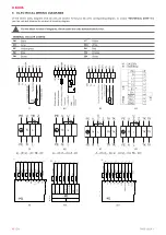
9. ELECTRICAL WIRING DIAGRAMS
On this section wiring diagrams of all fan units are present. To find your fan unit’s corresponding diagram, on section
find
your fan unit and observe the number of its wiring diagram.
For the latest version of diagrams, check under the units terminal block cover.
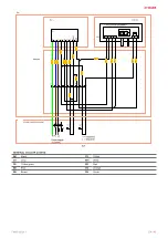
GENERAL COLOUR CODING
BK
Black
YE
Yellow
GY
Grey
WH
White
PE
Yellow-green
RD
Red
BU
Blue
OG
Orange
BN
Brown
GN
Green
/B
K
L1
1
2
Motor
K1
S1
#1
#2
#3
#4
#5
#6
#7
#8
Z
2
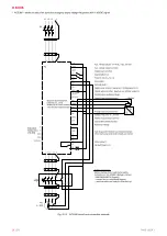
– BK;
U
2
– BU;
TB
– BN
U
2
– BK;
U
1
– BU;
Z
– BN.
Z
1
– BK;
U
2
– BU;
U
1
– BN;
Z
2
– OG;
TK
– WH.
W
1\
gr
ee
n/y
ell
ow
W
1\
bl
ue
W
1\
br
ow
n
SP
26
-b
W
1\
w
hit
e1
W
1\
w
hit
e2
W
2\
yell
ow
W
2\
bl
ue
W
2\
re
d
1
PE
-X1
2
1
N
2
1
L1
2
1
1
2
1
2
2
1
3
2
1
4
2
1
5
2
PE
N
L
NC
CO
M
0-
10V
GN
D
10
V
-M1
Red
0.5
Bl
ue
0.5
Yell
ow
0.5
White
1
White
1
Bl
ack
1
Bl
ue
1
Gr
een-
yell
ow
1
1
PE
-X1
2
1
N
2
1
L1
2
1
1
2
1
2
2
1
3
2
1
4
2
-M1
PE
N
L
Ta
cho
0-
10
V/P
W
M
GN
D
+1
0V
SP
23
-b
Red
0.5
Yell
ow
0.5
Bl
ue
0.5
White
0.5
Br
own
1
Bl
ue
1
Gr
een-
yell
ow
1
1
PE
-X1
2
1
L1
2
1
L2
2
1
L3
2
1
1
2
1
2
2
1
3
2
1
4
2
1
5
2
W
1\
gr/y
e
W
1\
bl
ac
k
W
1\
br
ow
n
W
1\
grey
W
3\1
W
3\2
W
2\1
W
2\2
W
2\3
PE
1-
L1
2-
L2
3-
L3
3-
NC
2-
COM
4-
Ai
n1
U(0-10V
)
3-
GND
5-
+10V
-M1
SP
27
-b
Black
0.5
Black
0.5
Black
0.5
Black
0.5
Black
0.5
Grey
1.5
Br
own
1.5
Black
1.5
Gr
een-
yellow
1.5
#9
#10
#11


