38
| EN
FANS v2024.1
•
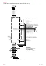
ACS380 – allows to select fan speed by changing output voltage frequency with 0-10VDC signal.
DR
AW
N
BY
CH
EC
KED
B
Y
SIG
NA
TU
RE
DU
TI
ES
/
NA
M
E
DA
TE
SA
LD
A
UA
B
Dr
aw
ing
#
Bo
ok
#
AP
PR
OV
ED
B
Y
76
5432
110
-1
FI
De
lta
3~
400
V
1
02
20
17-
09-
27
20
17-
09-
27
M
TK
U
V
W
PE
TK
TK
-M1
-Q2
-FI
L1
T1/U
L2
T2/V
L3
T3/W
PE
PE
PE
+24V
DGND
DCOM
DI1
DI2
DI3
DI4
DIO1
DIO2
DIO SRC
DIO COM
AI1
AGND
AGND
AO
AGND
SCR
+10V
RC
RA
RB
B+
A-
BGND
Shield
Termination
Aux. voltage 24 V DC, max. 200 mA
Aux. voltage output common
Digital input common
Stop (0)/Start (1)
Forward (0)/Reverse (1)
Run enable
External fault 1
Digital input function: Ramp set 1 (0)/Ramp set 2 (1)
Digital output function: Ready to run (0)/Not ready (1)
Digital output auxiliary voltage
Digital input/output common
Output frequency/Speed
reference (0...10 V)
Analog input circuit common
Two-wire sensor/transmitter
Analog input circuit common
Output frequency (0...20 mA)
Analog output circuit common
Signal cable shield (screen)
Reference voltage
Relay output 1
No fault [Fault (-1)]
Embedded
Modbus RTU
(EIA-485)
L1 L2 L3
1
2
3
4
5
6
PE
PE
13
14
+Q1
TK
TK
TK
TK
AI2
P
I
-
+
S+
SGND
S1
S2
Safe torque off function. Connected at factory.
Drive starts only when both circuits are closed.
1...10kOhm
3~ 400V
Safety instructions:
Before starting motor read the full safety
instructions in the ACS380 Hardware manual
(3AXD50000029274 [English]).
- connect fan by recomended diagram,
- read instruction and make the first start-up.
Fig. 8.2.3 ACS380 pinout and connection example


