EN |
23
FANS v2024.1
To prevent damage to the casing, only a product placed on a pallet should be lifted.
5.3. UNPACKING
Accessories may be packed together with the product. Prior to transporting the unit, the accessories should be unpacked
first.
•
After unpacking the unit, examine it to make sure that no damage was made during transportation. Installation of damaged units is not allowed!
• Before commencing the installation of the unit, please check if all ordered equipment has been delivered. Any deviation from the ordered equip-
ment list must be reported to the product supplier.
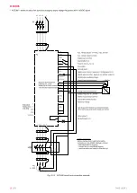
5.4. PIPING AND INSTRUMENTATION DIAGRAM
Availability and location of exact accessories provided as components in the diagrams may depend on fan unit model or installation purpose of
the unit. When air is supplied to the premises, air flow outlet should be connected to the premises and air damper should be connected to the air
flow inlet side. When air is extracted from the premises, air flow inlet should be connected to the premises and air damper should be connected
to the air flow outlet side.
0123
456712893
0917
082534713
410181
3 30
1930
0
935457
!
#
$
$
#
%5&
'
%5&
'
()*+-./()*+-.01/(23+-.
.+
-.--4.54
.6
-.--4.54
.6
8
)9:;:<
=
8)
8<
>?
@
AC<
:@
D=
8<
>
?@A
C
A;
=@D
=
E1F
)
G;H=
I
G;H=
0123
456712893
0917
082534713
410181
3 30
1930
0
935457
!
#
$
$
#
%5&
'
%5&
'
4531 6
$
(!(
$
(!(
$
1
(
(
8)*
+
,
,
./
0
1.
0/10
1
*
2
2
30
1
*
2
/0
2
30
9
8)4+5
0/10
Fig. 5.4.1
KF T120, KF T120 EC, KUB T120 fans
Fig. 5.4.2 VSVI EKO AL CPG fans
* U(p) is converted from U(f) to control fan speed by air flow
0123
456712893
082534713
410181
3 30
1930
0
935457
!
#
$
$
#
%5&
'
%5&
'
41(413(4(45
(451(431(4531(83(
)*))+*,+
*.
)*))+*,+
*.
/
012324
5
/0
/4
68
9
:;4
29
<5
/4
68
9
:;:35
9
<5
=>?
@3A5
C
0123
456712893
0917
082534713
410181
3 30
1930
0
935457
!
#
$
$
#
%5&
'
%5&
'
()*+()*-).+/)(012
3+/)(-).+/)4+/)4(
35
53556386
39
53556386
39
(
:;<=<>
?
(:
(@;>
A
;CA
D
EFGHF<D<?
IJ
6
K
6
L.
6
-
6
N
(>
OP
A
FQ>
<A
D?
(>
OP
A
FQF=?
A
D?
RL1
S=E?
:
S=E?
N
Fig. 5.4.3
VSA, VSA EKO, VSV, VSVI, VSVI AL, VSV EKO AL,
VSVI EKO AL, KUB EKO fans
Fig. 5.4.4
AKU, AKU EKO, VKAP 3.0, VKA EKO, VKS, VKSA fans
LIST OF INTEGRATED COMPONENTS
LIST OF OPTIONAL ACCESSORIES
AF
Air fan
F
Air filter
U(f)
Air pressure controller
RC3
Fan speed controller
W
Water heater
CO
Water cooler
E
Electrical heater
M
Air damper
U(p)*
Air flow controller
* U(p) is converted from U(f) to control fan speed by air flow.
For additional inputs / outputs of the exact fan unit, see section


