background image

28

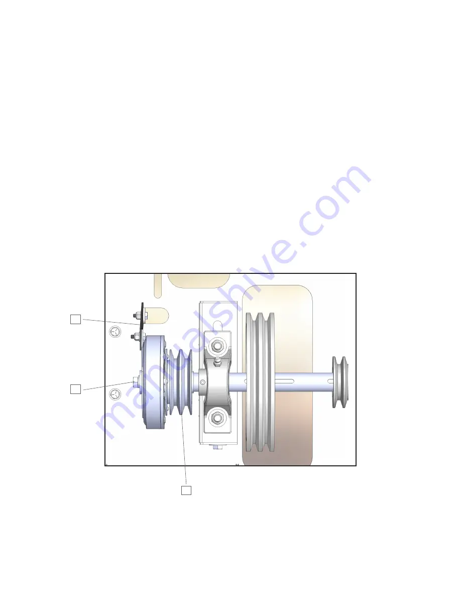
ELECTRO-MAGNETIC CLUTCH

The electro-magnetic clutch has no scheduled wear replacement parts and can only be replaced whenever 
field failures may occur. Refer to the following drawing and detailed instructions for removing the clutch from 
the shaft.

1.

 Disconnect wiring at clutch connector.

2.

 Remove torque arm attach bolt from clutch arm.

3.

 Remove drive belts from pulley. The pulley is part of the clutch assembly.

4.

 Remove the attach bolt, washer, & lock washer.

5.

  Slide clutch off clutch shaft. The use of a pry bar or similar device may be necessary to start clutch off shaft, 

wedge between bearing housing and clutch hub. Make sure that bearing shaft seal or clutch bearing seal 
does not get damaged.

6.

 Inspect clutch drive key, replace as required.

Note: Upon reassembly, make sure to add two drops of blue Loctite to threads of attach bolt. Be careful not 
to get Loctite on clutch shaft.

2

4

3

Summary of Contents for CertainTeed Volu-Matic 100

Page 1: ...Safety Information Volu Matic 100 Parts Service Accessories 863 294 3206 800 237 7841 www certainteedmachineworks com PLEASE READ THIS MANUAL BEFORE PLACING YOUR NEW VOLU MATIC 100 INSULATION BLOWING...

Page 2: ...he tank or operating the machine Fumes from fuel are explosive and can be fatal Follow all safety precautions when handling any type of fuel WARNING Recommended hose size type and length must be used...

Page 3: ...3 SPECIFICATIONS 4 INTRODUCTION 6 SAFETY 8 OPERATION 12 TROUBLESHOOTING 20 PREVENTIVE MAINTENANCE 24 PARTS DRAWINGS 30 WARRANTY 41 Table of Contents...

Page 4: ...L MACHINES 10 airlock air volume control system positive displacement blower electro magnetic clutches HEIGHT 68 LOAD HEIGHT 54 WIDTH 46 5 LENGTH 54 WEIGHT 850 lbs ELECTRICAL 12V DC MAXIMUM FEED RATES...

Page 5: ...E CORD DOUBLE POLE 150 1 EA 210031 STATOR BAR COVER PLATE 1 EA Operation Manual 1 EA 210471 ACC HOSE PACKAGE Not Included 162885 MARK II CLEAR HOSE 3 X 50 3 EA 210991 HOSE SLEEVE 3 2 EA 162482 2 5 3 W...

Page 6: ...esented to provide a basic description of the function and purpose of the Volu Matic 100 machine The Volu Matic 100 machine is principally designed to blow insulating materials into attics of resident...

Page 7: ...dicating that power is on for both the blower relay and remote control receptacle When the remote cord switch is moved toward the cord power is sent through the emergency stop buttons to the blower re...

Page 8: ...g displayed in a prominent place Do not remove modify or deface the warning label WARNING if any foreign object should enter the machine push an emergency stop button in off turn off the master switch...

Page 9: ...at the operator is aware of other hazards associated with the use of the machine You will see the following warnings on the machine Do not remove modify or deface the warning labels The purpose of thi...

Page 10: ...The top of the machine does not require guarding when correctly mounted in the contractor s truck or trailer If the machine is installed so that the top is exposed such as in a manufacturing plant or...

Page 11: ...oo close to the machine objects falling into machine a machine component breaks a material hose becomes disconnected anything requiring immediate stopping of the machine You will have to restart the e...

Page 12: ...12 Operation...

Page 13: ...use in each component 4 Check material conditioning slide gate and air bleed control valve position Check the recommended start settings chart for proper position 5 Make sure all guards are in place a...

Page 14: ...tisfactorily cycle the switch toward the end of the housing and the blower and machine mechanisms will operate simultaneously 8 Take some time to get to know the Volu Matic 100 machine Engage and dise...

Page 15: ...ngine speed for machine operation Reduce machine speed approximately 20 percent for side wall operation 2 Vary the air bleed pressure first If you cannot get the desired results by opening or closing...

Page 16: ...the hose does not have a short radius bend 3 blowing hose minimum 150 3 rubber hose sleeve 3 2 5 reducer 2 5 blowing hose minimum 150 For side wall operation connect hose to airlock feeder as shown i...

Page 17: ...th and proper hose while material is being blown Always start the adjustment with the air bleed control valve in the fully closed position If the air flow and pressure deliver the desired results with...

Page 18: ...00 machine This moves the operator closer to the rotating components in the hopper and provides a way to lose balance and fall Load one to two bags of material into the hopper being particularly caref...

Page 19: ...ag at a depth of 11 5 and a weight 0 427 lbs per sq ft to achieve an insulation value of R 30 Fiber must be worked or conditioned by your Volu Matic 100 machine to achieve coverage Coverage decreases...

Page 20: ...20 Troubleshooting...

Page 21: ...mergency stop button 3 or 4 is not pushed in off d Check remote cord connection 6 e Remote cord or connection defective 3 Blower will not operate a Check clutch electrical connections b Check that blo...

Page 22: ...connections d Material hose plugged e Airlock feeder components seals worn out or damaged F Blower defective worn or damaged 5 No Material Flow a No material in hopper b Check clutch electrical connec...

Page 23: ...23...

Page 24: ...24 Preventive Maintenance...

Page 25: ...ese screens clean 2 Visually inspect and remove any foreign objects that may have entered the machine such as pieces of bag rags razor knife etc 3 Make sure emergency stop buttons are functional 4 Che...

Page 26: ...als P N 210358 before the job is started Make sure all power is disconnected distributor wire on engine master switch off remote cord unplugged etc Remove necessary guards to do the job after power is...

Page 27: ...e of feeder barrel Apply never seize lubricant on inlet bearing race 6 Insert rotor assembly into airlock feeder barrel rotating counterclockwise while pushing with free hand Make sure bearing seal at...

Page 28: ...emove drive belts from pulley The pulley is part of the clutch assembly 4 Remove the attach bolt washer lock washer 5 Slide clutch off clutch shaft The use of a pry bar or similar device may be necess...

Page 29: ...The proper oil level is at the bottom of the plug half way up the gearbox housing After 200 hours of operation drain while warm and refill with fresh lubricant Thereafter change every six months or 25...

Page 30: ...30 Parts Drawings...

Page 31: ...31...

Page 32: ...UNTER SUNK 1 000 210951 BEARING 2 HOLE COUNTER SUNK 1 000 V100 HOPPER COMPONENTS DO NOT SCALE DRAWING VM100 HOPPER SHEET 1 OF 1 8 12 2022 AGA UNLESS OTHERWISE SPECIFIED SCALE 1 15 REV DWG NO B SIZE TI...

Page 33: ...IS DRAWING IS THE SOLE PROPERTY OF CERTAINTEED MACHINE WORKS ANY REPRODUCTION IN PART OR AS A WHOLE WITHOUT THE WRITTEN PERMISSION OF CERTAINTEED MACHINE WORKS IS 1 5 16 18 NYLOCK NUT FEEDER OUTLET EN...

Page 34: ...210781 PLEXIGLASS CVR W FELT TAPE VOLU MATIC 100 SHREDDER DO NOT SCALE DRAWING VM100 SHREDDER SHEET 1 OF 1 8 12 2022 AGA UNLESS OTHERWISE SPECIFIED SCALE 1 6 REV DWG NO B SIZE TITLE NAME DATE CHECKED...

Page 35: ...G 162441 H BUSHING 1 BORE 161870 QTY 2 A39 BELT GRIPBELT 210461 MAIN CLUTCH SHAFT 162611 QTY 2 BEARING 1 187 P BLOCK 159759 2BK90H PULLEY USE H BUSHING 162443 H BUSHING 1 3 16 BORE 210371 ROOTS BLOWER...

Page 36: ...SHER 1 2 13 NYLOCK NUT 160631 4017 CHAIN ROLLER 40 10FT BOX 160631 4017 CHAIN ROLLER 40 10FT BOX 160631 4017 CHAIN ROLLER 40 10FT BOX VOLU MATIC 100 CHAIN DRIVE DO NOT SCALE DRAWING VM100 CHAIN DRIVE...

Page 37: ...210058 1 1 2 X 2 NIP THRD ONE END 210317 ROOTS BLOWER RH ROTATION 36U RAI W OIL VOLU MATIC 100 CHAIN DRIVE DO NOT SCALE DRAWING VM100 AIR STREAM SHEET 1 OF 1 8 12 2022 AGA UNLESS OTHERWISE SPECIFIED...

Page 38: ...ECTRICAL SHEET 1 OF 1 8 12 2022 AGA UNLESS OTHERWISE SPECIFIED SCALE 1 8 REV DWG NO B SIZE TITLE NAME DATE CHECKED DRAWN BY FINISH DIMENSIONS ARE IN INCHES TOLERANCES FRACTIONAL 1 32 ANGLE 1 TWO PLACE...

Page 39: ...A VOLU MATIC 100 MATERIAL 03 THREE PLACE DECIMAL DRAWN BY FINISH 1 01 DIMENSIONS ARE IN INCHES TOLERANCES FRACTIONAL 1 32 ANGLE 1 THE INFORMATION CONTAINED IN THIS DRAWING IS THE SOLE PROPERTY OF CER...

Page 40: ...40 DATE JOB DESCRIPTION PERFORMED BY Please contact Customer Service for information on any components or options not listed on this manual...

Page 41: ...ced on a regular basis due to normal wear and usage including but not limited to seals feeder shredder auger fuses switches clutches hoses shaft seals chains belts sprockets pulleys bearings cables an...

Page 42: ...rinted in the USA Code No 08 03 1603 US EN CertainTeed CE I LI N G S D ECK I N G FE N CE GY P S U M I N S U L ATIO N R AI LI N G ROO FI N G S I D I N G TR I M 20 Moores Road Malvern PA 19355 800 233 8...

Reviews: