


Return to Table of Contents
Ref: SafetyLink Pty Ltd Permanent Ladder System
Page 24 of 36
Doc ID: MKT-471 Version: 19.0
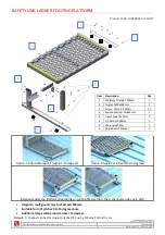
LADDER MIDWAY REST PLATFORM
Product Code: LADER002.PLT.MID
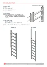
COMPONENTS
1 x Angle Bar 50mm
1 x Frame A
1 x Frame B
18 x M10x70mm Bolts with Washer/Nyloc Nut
2 x M10x80mm Bolts with Washer/Nyloc Nut
10 x 10Gx25 Tek Screws
6 x Horizontal Handrails
4 x Vertical Handrails
8 x Junction Coupling Pieces with M8 socket screws
3 x Toe Boards
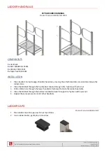
FIXINGS
FIXING TO STRUCTURE (NOT SUPPLIED)
Metal:
M12 Bolts fixed through the structure.
Concrete:
M12 Masonry Bolts or equivalent.
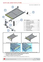
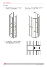
ASSEMBLY
Assemble the rest platform at ground level.
All M8 fixings to be torque tighten to 15Nm.
1. Organise the frame B in right orientation to install
the top ladder at decking.
2. Fix the frame A into frame B by using two (2)
M10x70mm bolts.
3. Install the bracing between frame A and B by using
four (4) M10x70mm bolts.
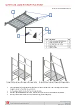
4. Fix all handrails together with junction coupling. All
the M8 socket screws in the junction coupling to
be torque tightened to 15Nm.
5. Install the vertical and horizontal handrails with
junction coupling between frame A and B by using
twelve (12) M10x70mm bolts.
6. Install the Toe boards between frame A and B by
using eight (8) 10Gx25 Tek Screws.


