System Information
Select the System Information icon to display the System,
History, Modules, and Authorized menus.
These menu options display unique information and history
about the DVR unit.
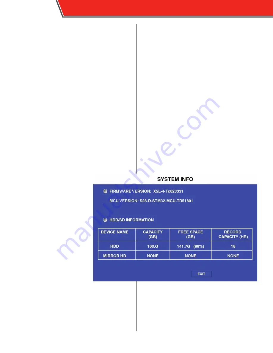
System
The System menu displays the firm-
ware version and information on the
SD card.
FIRMWARE VERSION:
The version of
firmware currently installed.
MCU VERSION:
The MCU feature is not
active at this time.
DEVICE NAME:
Displays the name of
the storage unit.
CAPACITY:
Displays the overall capac-
ity of the storage unit, in gigabytes
(GB).
FREE SPACE:
Displays the remaining
storage capacity of the storage unit, in
gigabytes (GB).
RECORD CAPACITY:
Displays the over-
all recording capacity of the storage
device (in hours), based on the capacity
and setting made in the configuration menus.
If information about a storage device
is displayed in this menu, it is operating
as normal.
54
ICOP PRO USER GUIDE
Summary of Contents for ICOP PRO
Page 1: ...ICOP PRO USER GUIDE...
Page 59: ...ICOP PRO USER GUIDE 57...
Page 61: ...Appendix B Dimensions DVR Power Control Monitor ICOP PRO USER GUIDE 59...
Page 62: ...ICOP PRO USER GUIDE 60...
Page 65: ...ICOP PRO USER GUIDE 63...