background image


www.saferoads.com.au


T      

1800 060 672 


[email protected]


Australian Version 3.1 

June 2020 

Page 57 


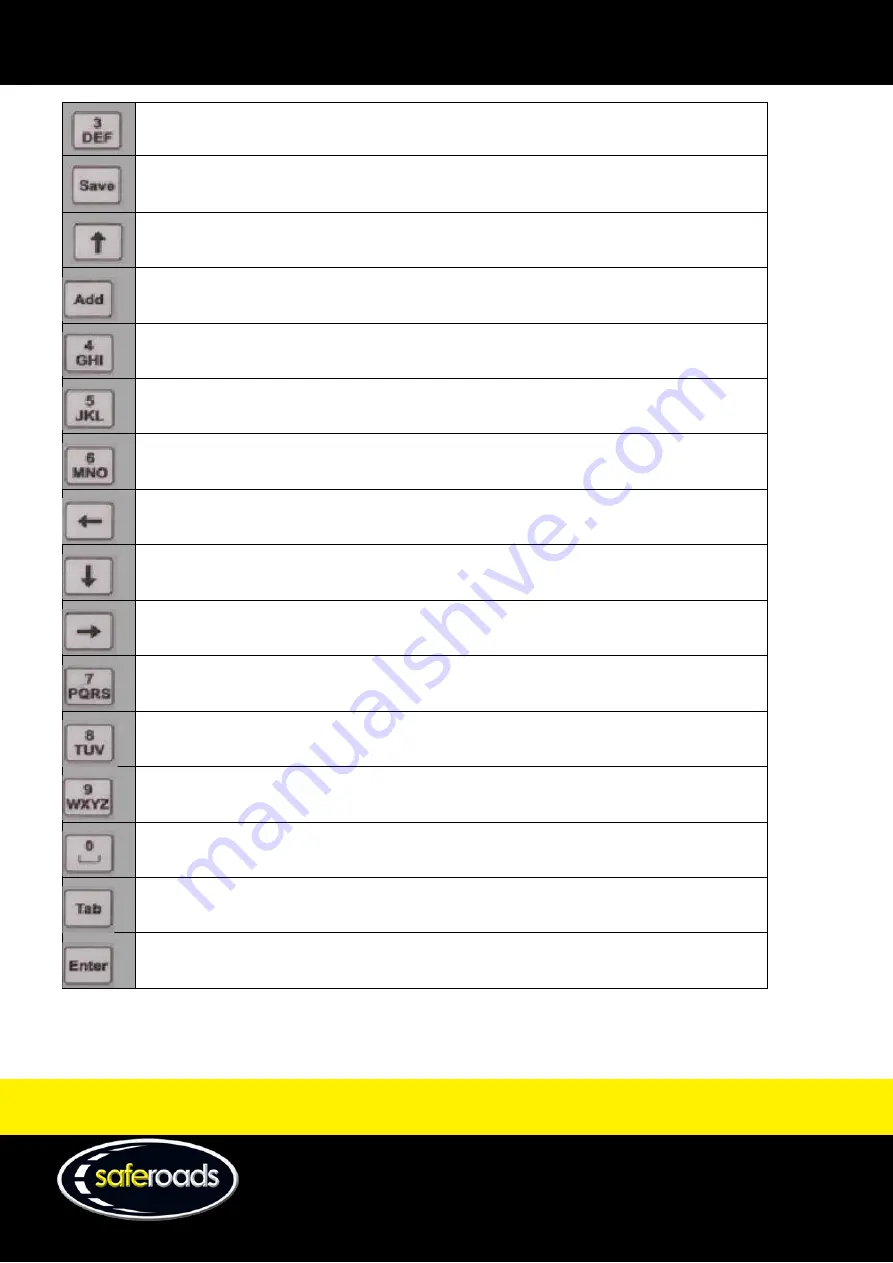
D, d, E, e, F, f, 3, ^, &, * 


Save the current VMS file. 


Move Cursor Arrow UP. 


Add line (Enter) 


G, g, H, h, I, i, 4, -, _, = 


J, j, K, k, L, l, 5, +, /, < 


M, m, N, n, O, o, 6, >, `, ~ 


Move Cursor Arrow LEFT. 


Move Cursor Arrow DOWN. 


Move Cursor Arrow RIGHT. 


P, p, Q, q, R, r, S, s, 7, { 


T, t, U, u, V, v, 8, \, |, } 


W, w, X, x, Y, y, Z, z, 9, " 


0, <space between characters> 


Skip line 


Enter the information. 


Summary of Contents for Zone 2 VMS

Page 1: ...W www saferoads com au T 1800 060 672 E sales saferoads com au Australian Version 3 1 June 2020 VMS Manual ...

Page 2: ...How to Set Alarms 11 Deployment 12 Pack Up 12 Operation Guide 13 Solar Panels 13 Solar Panel Tilt Switch 13 Solar Panel Pivot 14 Mast 15 Mast Assembly 15 Mast Locking Pin 15 Mast Pivot Lock 16 Mast Up Down Switch 16 Hydraulic Reservoir and Mast Motor 16 Trailer 17 Stabilising Jacks 17 Jockey Wheel 18 Transport Support 18 Front Toolboxes 19 Rear Toolboxes 19 Display Panel 20 Display Panel Case 20 D...

Page 3: ...ngs Page 36 Alarms Page 37 Favourites Page 38 Admin Users Page 39 Support Pages 40 Manuals Page 40 Newsletter Page 40 Support Page 41 Contact Page 42 Manage User Page 42 Maintenance 43 Opening the Display Case 43 Removal and Installation 44 LED Panel Removal and Installation 44 SIM Card Removal and Installation 46 Motherboard CPU Removal 47 Modem Removal and Installation 48 Reset Procedure for VMS...

Page 4: ... Manager 54 Introduction 54 Power On 55 Button Description 56 Built in Library Picture Selection 58 Menu Options 63 File Menu 63 Operate Menu 65 Set Menu 69 Help Menu 72 Sending Files to the VMS Display 72 Send Built In Library File to the VMS Display 72 Create a New VMS File 74 Personal Protective Equipment 77 ...

Page 5: ...d Essential with each model being available in either amber or five colour lighting displays The Classic model differs from the Essential model in terms of the inclusion of extra features such as an onboard battery charger an onboard message manager a spare wheel fully sealed toolboxes and the ability to tilt and rotate the solar panels These all come standard on the Classic model and the first th...

Page 6: ... 2020 Page 5 Quick Start Guide How to Login to Zone Website 1 Go to the website http zonecloud com au 2 Enter email address 3 Enter password Figure 1 4 Click on Log in button How to Display a Simple Message 1 Select Messages from the menu or the Editor icon from the Zone main screen Figure 2 ...

Page 7: ... Library Favourites or Create a custom image using the drawing tools 5 Click on the Add button to move the image to frames Figure 6 6 Click on the Send to VMS button Ensure the VMS Display is switched on so the message can be displayed Figure 7 7 Select the VMS to play the message on Multiple VMS can be added by clicking on the Select VMS text box Figure 3 Figure 4 Figure 5 ...

Page 8: ...Australian Version 3 1 June 2020 Page 7 Figure 8 8 Click on the Send button to send the message to the VMS How to Adjust Settings 1 Select Settings from the menu or the Settings icon from the Zone main screen 2 Select the Project 3 Select the VMS Figure 10 Figure 9 ...

Page 9: ...aferoads com au Australian Version 3 1 June 2020 Page 8 4 Adjust the settings Figure 11 5 Click on the Save button to send the settings to the VMS How to Setup Radar 1 Select Radar from the menu or the Radar icon from the Zone main screen Figure 12 ...

Page 10: ...e VMS 4 To display an Approach Message a Drag an image from the Library to Approach Message image box Figure 14 b Enable Approach Message by turning the switch on Figure 15 5 To display Correct Speed a Drag an image from the Library to Correct Speed image box Figure 16 b Enable Correct Speed by turning the switch on Figure 17 Figure 13 ...

Page 11: ...lay Over Speed a Drag an Image from the Library to Over Speed image box Figure 18 b Enable Over Speed by turning the switch on Figure 19 7 Adjust the Radar Settings Figure 20 8 To enable radar logging turn the Enable Radar Log switch on Figure 21 9 Click the Send to VMS button to save the Radar Settings Figure 22 ...

Page 12: ...une 2020 Page 11 How to Set Alarms 1 Select Settings Alarm from the menu or the Alarms icon from the Zone mainscreen and the Alarm tab 2 Select the Project 3 Select the VMS 4 Modify the alarm settings Figure 25 5 Click on the Save button to save the alarms for the VMS Figure 23 Figure 24 ...

Page 13: ...MS to head height 7 Watch out for toolbox when lifting lowering mast 8 Unlock the Mast Pivot Lock 9 Rotate to desired angle facing the desired traffic Slight angle is fine 10 Check above if clear lift fully or as desired 11 Place all locks into position toolboxes front screen shaft lock important Pack Up 1 Lower the mast to head height 2 Unlock the Mast Pivot Lock and straighten the VMS 3 Lower th...

Page 14: ... toolbox between the VMS Display Switch and the Mast Up Down Switch It is employed to tilt the solar panels to an angle to gain maximum power production for the solar panels The optimum position is to set the panels facing north and tilted up to an angle of 30 degrees regardless of the orientation of thetrailer Operation of the solar panel tilt will require the VMS Display Switch to be in the ON p...

Page 15: ... optimum production from the panels To use this feature simply acquire the wheel brace provided in the front driver s side toolbox to turn the Solar Panel Pivot in the direction necessary to gain maximumsunlight The solar panels can only be pivoted once they have been tilted It is recommended to clean and wash down the solar panels every 30 days to decrease the amount of dust and ingress as it can...

Page 16: ...d or lowered depending on the specific site requirements To control the height of the mast simply toggle the Mast Up Down Switch located in the driver s sidetoolbox Figure 29 Mast Locking Pin The Mast Locking Pin is a safety feature used when the trailer is in transit to prevent the mast from rising When the mast is lowered simply secure the Mast Locking Pin into the recess and this will stop the ...

Page 17: ...display and when transporting the board Figure 30 Mast Up Down Switch The Mast Up Down Switch is located in the front passenger side toolbox to the right of the Solar Panel Tilt Switch It is used to operate the Mast to increase or decrease the height of the Display Panel To operate the Mast Up Down Switch the VMS Display Switch must be in the ON position Engage the switch into either the UP or DOW...

Page 18: ...cated on each corner of the trailer to provide stability and levelling when the VMS trailer has been parked into the required position or on uneven ground They are constructed of heavy duty steel and have a smooth operating Screw Jack handle The jacks can be extended to provide further stability when in strong winds To rotate the Stabilising Jacks from the horizontal position to the vertical posit...

Page 19: ...w ball The Screw Jack can then be used to gently lower the trailer nose onto the tow ball Once securely attached to the towing vehicle the Jockey Wheel s jacking action is fully retracted into its horizontal position for transportation Ensure the Jockey Wheel is seated in the horizontal position prior to transporting the trailer Figure 34 Transport Support The Transport Support has been built onto...

Page 20: ...Hydraulic Reservoir and Mast Motor The front driver s side toolbox consists of the wheel brace and manual for the VMS Figure 36 Rear Toolboxes The rear toolboxes are home to either two Essential Amber three Essential 5 Colour or four Classic 12V batteries required to power the VMS display and the 240V Battery Charger where fitted required to power the batteries Note The 240V on board Battery Charg...

Page 21: ...n be fitted with padlocks for added security for the case and the sensitive equipment held within Figure 38 LED Panels There are 42 identical LED panels made up of 32 LED assemblies on each panel that consist of 14 LED light bulbs per LED assembly VMS Display Switch The VMS Display Switch is located in the front passenger side toolbox to the left of the Solar Panel Tilt Switch and supplies power t...

Page 22: ...s a control device used specifically for uploading built in pictures and built in or manual text to the Display Panel Note The Onboard Message Manager comes standard on the Classic model and is optional on the Essential model Figure 39 3G GPS Assembly The 3G GPS assembly is made up of an antenna modem and SIM card The antenna performs both 3G and GPS functionality and connects directly to the CPU ...

Page 23: ... VMS unit as it controls what is viewed on the Display Panel distributes power to the board and connects directly with the GPS antenna and the radar where fitted Figure 41 Radar where fitted The Radar Unit is located on the top right hand corner of the Display Panel Case It tracks and stores the speed of vehicles approaching the VMS board up to 100m away It is controlled from the Zone VMS online m...

Page 24: ...roads com au T 1800 060 672 E sales saferoads com au Australian Version 3 1 June 2020 Page 23 Website Login Page Figure 43 1 Email 2 Password 3 Login Note A valid account is required to login to the Zone website ...

Page 25: ...oard provides links to the most commonly used features on the website 1 Status page 2 Maps page 3 Editor page 4 Radar page 5 Settings page 6 History page 7 Scheduling page 8 Alarms page 9 Contact Us page 10 Diagnostics page 11 Project Shows a list of all projects available to the user 12 VMS Shows a list of all VMS in the selected project ...

Page 26: ... IMEI number on the VMS modem this is a unique number for every VMS SIM Number SIM phone number Serial Number VMS serial number on the main control board Brightness brightness percentage of the VMS Battery Voltage GPS GPS status Signal VMS signal strength Display Type type of VMS Last Connect Time the last time the VMS connected to the Zone server 2 Close button Link back to the dashboard 3 VMS qu...

Page 27: ...orange battery 50 green battery 75 green battery and 100 green battery 6 VMS signal strength Displays the signal strength of the mobile phone signal on the VMS There are five levels 0 0 bars 25 1 bar 50 2 bars 75 3 bars and 100 4 bars 7 VMS GPS signal on off Displays if there is a GPS signal on the VMS The green world icon represents GPS has a location fix whereas the red world icon represents no ...

Page 28: ...mation of where the VMS is located 1 Maps Map of the VMS locations 2 Close Button Link back to the Dashboard 3 VMS Address and Information Provides basic information of the VMS including current playing message VMS name VMS address location IMEI number battery voltage and brightness percentage The Zoom To button will zoom into street level for the VMS ...

Page 29: ...e allows the user to create a message to play on the selected or multiple VMS from the current project 1 Library Favourites Library shows predefined messages These cannot be edited or deleted Favourites shows messages that have been added to favourites These can be removed from Settings Favourites page 2 Close Button Link back to the dashboard ...

Page 30: ...ld the left mouse button down inside the Editor canvas where the middle of the circle will be located drag to the size of the desired circle and release the left mouse button The Line tool will allow the user to draw a line Click and hold the left mouse button down inside the Editor canvas where the line will start drag to the size of the desired line and release the left mouse button The Fill too...

Page 31: ...e Radar page Radar messages can be deleted from Settings Favourites page o Note The Message does not need to be added to the Frames section to be saved Save Message to Favourites o The Message is saved to the Library Favourites section above To see the Message make sure Favourites is selected at the top Favourites can be deleted from Settings Note Messages do not need to be added to the Frames sec...

Page 32: ...he File Name Display Now is the name of the Message when using the Send Frames button 20 Send Frames Send the Frames to the VMS to play straight away Select which VMS in the Project to play Note The Message must be added to the Frames section for it to be played 21 Text Line Text to enter onto the Editor Canvas Four lines of text can be entered if the line height is set to 4 22 Text Colour Text Co...

Page 33: ...ralian Version 3 1 June 2020 Page 32 Scheduling Page Figure 48 The scheduling page provides information of the selected VMS schedule 1 Schedule 2 Close button Link back to the dashboard 3 File name File name of the scheduled message for the selectedVMS 4 Edit schedule ...

Page 34: ... Day assigned o Day of the week the message will play Update o Updates the message in the scheduler Note When no information is entered into start date end date start time end time and day assigned then the message will always play 5 Delete schedule Deletes the scheduled message from the selected VMS 6 Read schedule in editor Show the scheduled message in the editor page 7 Skip to first page If th...

Page 35: ...Enable Radar Log 4 Speed Limit 5 Display Speed 6 Correct Speed Min the minimum speed allowed that will display the Correct Speed message on the VMS 7 Correct Speed Max the maximum speed allowed that will display the Correct Speed message on the VMS 8 High Speed Cut Off 9 Approach Message On Off 10 Approach Message Display 11 Correct Speed On Off 12 Correct Speed Display 13 Over Speed On Off 14 Ove...

Page 36: ...800 060 672 E sales saferoads com au Australian Version 3 1 June 2020 Page 35 15 Radar Log 16 Save Radar Troubleshooting Page Figure 50 The troubleshooting page on the Zone website shows a list of issues logged by the VMS boards ...

Page 37: ...rsion 3 1 June 2020 Page 36 Settings Page Figure 51 Settings 1 Settings 2 Close button 3 Display 4 Brightness Control 5 Max Brightness 6 Max Brightness 7 50 Dimming Override 8 Dimming Start Time 9 Dimming End Time 10 Time Zone 11 Day Light Savings 12 VMS Time 13 VMS Start Time ...

Page 38: ...1 June 2020 Page 37 14 VMS End Time 15 Save button Alarms Page Figure 52 Alarms 1 Alarm 2 Close button 3 Email 4 Over Voltage On Off 5 Over Voltage value 6 Under Voltage On Off 7 Under Voltage value 8 GPS Move On Off 9 GPS Move value 10 Over Temperature On Off 11 Over Temperature value ...

Page 39: ...ales saferoads com au Australian Version 3 1 June 2020 Page 38 12 Auto Pixel Detection On Off 13 Auto Pixel Detection value 14 Save Favourites Page Figure 53 Favourites 1 Favourites 2 Close button 3 VMS message 4 Radar message 5 Delete button ...

Page 40: ...W www saferoads com au T 1800 060 672 E sales saferoads com au Australian Version 3 1 June 2020 Page 39 Admin Users Page Figure 54 User Administration 1 Create New 2 User details 3 Edit 4 Delete ...

Page 41: ...2 E sales saferoads com au Australian Version 3 1 June 2020 Page 40 Support Pages Manuals Page Figure 55 Manuals regarding VMS products are located on this page Newsletter Page Figure 56 Any newsletter updates will be posted to this page ...

Page 42: ...W www saferoads com au T 1800 060 672 E sales saferoads com au Australian Version 3 1 June 2020 Page 41 Support Page Figure 57 This page allows the user to contact support in the case of any issues ...

Page 43: ... 1800 060 672 E sales saferoads com au Australian Version 3 1 June 2020 Page 42 Contact Page Figure 58 Saferoads contact information is located on this page Manage User Page Figure 59 This page is used to reset user passwords ...

Page 44: ...m au Australian Version 3 1 June 2020 Page 43 Maintenance Opening the Display Case 1 Unlatch the Display Panel Locks from the Display Panel Case Figure 60 2 Open the Display Panel Case 3 Lock in the supporting arms of the Display Panel Case Figure 62 Figure 61 ...

Page 45: ... Panel Case as outlined on page 43 of this manual 2 Using a pair of needle nose pliers remove the two fuses located at the bottom right hand corner of the Display Panel Case to ensure the main source of power is disconnected from thecircuit Figure 63 3 Locate the panel s to be removed 4 Using needle nose pliers unlatch the securing pins in the panel Figure 64 5 Pull the LED panel away from the Dis...

Page 46: ...h the two securing pin clips on the plug to the rear LED panel Figure 66 7 Disconnect the plug from the LED panel 8 Replace the two fuses and backup battery connection 9 Close the Display Panel Case and latch the Display Panel Locks 10 For installation procedure complete steps in the reverse order Plug Figure 67 ...

Page 47: ...d from the modem complete the followingprocedure 1 Open the Display Panel Case as outlined on page 43 of this manual 2 Eject insert SIM card by pressing the SIM card 3 Push the reset button on the motherboard and check LED indicators as per the troubleshooting section on page 53 Figure 69 4 Close Display Panel Case and latch the Display Panel Locks Figure 68 ...

Page 48: ...t hand corner of the Display Panel Case to ensure no power is connected to the circuit 3 Label the eight wires on the terminals on the motherboard as in Figure 70 4 Using a small Phillips head screwdriver unscrew disconnect the wires from the motherboard CPU in the following order a Battery Power Red b Battery Power Black c Solar Panel Power Red d Solar Panel Power Black e Load Red f Load Black if...

Page 49: ...lay Panel Case 8 Replace fuses 9 Close Display Panel Case and latch the Display Panel Locks 10 For installation procedure complete steps in the reverseorder Modem Removal and Installation 1 Open the Display Panel Case as outlined on page 43 of this manual 2 Using needle nose pliers remove the two fuses located at the bottom right hand corner of the Display Panel Case to ensure the main source of p...

Page 50: ...d then smoothly push the tool to pull the cover and disengage the cover holes from the socket bumps Figure 73 Repeat the same operation on each side of the cover Do not apply excessive force that may damage the cover or the socket Remove the modem from the socket as illustrated in Figure 74 Figure 74 4 To insert the modem follow this procedure Check the alignment of pin 1 on both the module and th...

Page 51: ...age 50 Figure 75 Put the module down in the socket Use vertical motion to insert the module Figure 76 Check the orientation of the cover based on the location of pin 1 Figure 77 Smoothly press the cover onto the Snap in socket The cover should be properly aligned with pin 1 of the module Figure 78 ...

Page 52: ...020 Page 51 Check that the cover holes are locked on the socket bumps on all sides Figure 79 5 Replace fuses and close Display Panel Case and latch the Display Panel Locks 6 Reset CPU as per the reset procedure for VMS as detailed in Figure 67 on page Error Bookmark not defined of this manual ...

Page 53: ... the battery and the red lead of the multimeter on the red terminal of the battery 5 The multimeter should now display the batteryvoltage 6 If the battery voltage is greater than 10 5V the batteries areserviceable 7 If the battery voltage is less than 10 5V it is recommended to put the batteries on charge Testing SIM Card Serviceability To test the serviceability of the SIM card complete the follo...

Page 54: ... Saferoads support o If no voltage present there is likely to be a wiring or solar panel issue GREEN solar charge working 3G connection LED indicator L2 RED communication issue with modem o Possible 3G network issue unable to connect to Telstra network Confirm connection to network o If network connection OK contact Saferoads support GREEN Connection to 3G network OK Data communication indicator R...

Page 55: ...f over 100 single and multi frame VMS files and can create modify save and delete new VMSfiles With its own power supply and hardwired input into the motherboard the message manager will always be available to display VMS files sent directly to the VMSboard The message manager has connections located on the top side of theunit COM IN Used to communicate directly with the VMS board COM OUT Used to ...

Page 56: ...shown Figure 82 When switched on a loud beep will sound and the user will be taken to the passwordscreen Using the keys input the password if required then push enter the default password for all message manager units is 000000 Figure 83 Once the password has been entered the F1 shortcut screen will be visible Figure 84 Pushing the escape key will return the user to the menu option area Power Swit...

Page 57: ...erated when using the message manager Figure 85 Their function s are as follows Not used in the current set up Not used in the current set up Exit the Current Menu Shortcut Menu Send the current VMS file to the VMS display Preview the current VMS file on the Message Managerdisplay Change the font when creating a new message Delete the previous character 1 A a B b C c 2 ...

Page 58: ... 57 D d E e F f 3 Save the current VMS file Move Cursor Arrow UP Add line Enter G g H h I i 4 _ J j K k L l 5 M m N n O o 6 Move Cursor Arrow LEFT Move Cursor Arrow DOWN Move Cursor Arrow RIGHT P p Q q R r S s 7 T t U u V v 8 W w X x Y y Z z 9 0 space between characters Skip line Enter the information ...

Page 59: ...u Australian Version 3 1 June 2020 Page 58 Built in Library Picture Selection See Send Built In Library file to the VMS Display on page 71 for detailed instructions on how to use this feature 001 002 003 004 005 006 007 008 009 010 013 014 016 017 018 019 020 021 ...

Page 60: ...W www saferoads com au T 1800 060 672 E sales saferoads com au Australian Version 3 1 June 2020 Page 59 022 023 024 025 026 027 028 029 030 031 032 033 034 035 036 037 038 039 ...

Page 61: ...W www saferoads com au T 1800 060 672 E sales saferoads com au Australian Version 3 1 June 2020 Page 60 040 041 042 043 044 045 046 047 048 049 050 051 052 053 054 055 056 057 058 059 060 ...

Page 62: ...W www saferoads com au T 1800 060 672 E sales saferoads com au Australian Version 3 1 June 2020 Page 61 061 062 063 064 065 066 067 068 069 070 071 072 073 074 075 076 077 078 ...

Page 63: ...W www saferoads com au T 1800 060 672 E sales saferoads com au Australian Version 3 1 June 2020 Page 62 079 080 081 082 083 084 085 086 087 088 089 090 ...

Page 64: ...settings 4 Help basic descriptions of the keys used on the message manager Figure 86 File Menu The file menu has six selectable options 1 Program Message 2 Creat Modi Message 3 Add to Program Msg 4 Previews Message 5 Delete File 6 Back Figure 87 Program Message Push enter with this option highlighted to go to the built in library list where pre programmed VMS files can be sent to the VMS display N...

Page 65: ...a New VMS File section located on page 73 for detailed instructions on how to use this feature Figure 89 Add to Program Msg The add to program message will add the selected frame to current message on the VMS display This feature is used to join multiple built in librarypictures Figure 90 Preview Message The preview message option allows the user to preview the built in library files based on thei...

Page 66: ...rsonalise the built in library bydeleting some of the built in library files that are not required Figure 92 Back This option will take the user back to the menu screen Figure 93 Operate Menu The operate menu has 10 selectable options 1 Playing File Name 2 Del Play List 3 Del All Messages 4 Sign Config 5 Sign Information 6 Sign Test 7 Brightness Adj 8 Flash Light 9 Speed Limit 10 Back ...

Page 67: ...e name option will read the data from the motherboard and will display the current file sent to the VMS display Figure 95 Del Play List Delete playlist will delete the current file playing on the VMSdisplay Figure 96 Del All Messages Delete all messages will delete all messages currently saved to theinternal memory of the message manager Figure 97 ...

Page 68: ...ardware Name Width Height IP address GGUU settings Figure 98 Sign Information The sign information option allows the user to view the following information from the CPU Stats Inside temperature Outside temperature Figure 99 Sign Test The sign test option allows the user to complete three individual tests on the VMS display Check the horizontal and vertical alignment and ensure all LEDs are working...

Page 69: ...s adjust option allows the user to set a maximum brightness to the LED panels or set the brightness to Auto Note The recommended setting for Brightness Adjust is Auto Figure 101 Flash Light This feature is currently not used Figure 102 Speed Limit This feature is currently not used Figure 103 Back Select this option to return to the menuscreen ...

Page 70: ...ns in the set menu 1 Select Language 2 Config Sign 3 Set Date and Time 4 LCD Set 5 Display Format 6 Beep On Off 7 Password Setting 8 Communication Test Figure 105 Select Language The language select option allows the user to change the language set up on the message manager The available languages are Chinese English Spanish German andPortuguese Figure 106 ...

Page 71: ...unless advised by a technical staff member Figure 107 Set Date and Time The set date and time option allows the user to change the date time and time zone relative to where the user is located Figure 108 LCD Set The LCD set option allows the user to either turn on or off the backlight on the message managerdisplay Figure 109 Display Format The display format option allows the user to enable or dis...

Page 72: ...e beep for every button selection on the message manager Figure 111 Password Setting The password setting option allows the user to either amend the current password or turn the current password on or off when applying power to the message manager Figure 112 Communication Test The communication test option allows the user to test the connection between the message manager and the CPU Figure 113 ...

Page 73: ...ger can send built in library files and newly created VMS files to the VMS display The user can also save custom made files created on the message manager to the library to provide easy access to frequently usedfiles Send Built In Library File to the VMS Display To send a built in library file to the VMS display complete the followingsteps 1 Power on the message manager as per the power onsection ...

Page 74: ...d frame to be displayed on the VMS board Figure 117 4 If a second frame is available a black arrow will appear in the bottom left hand corner above the file path area Use the left and right arrow keys to view each frame Figure 118 5 Once the desired file has been located the user can then a Push enter and a new screen will appear requesting Send It Push enter againto send the file Figure 119 ...

Page 75: ...o the VMS display Figure 120 6 After the message manager completes a series of tests the VMS display will change to the selected file Figure 121 Create a New VMS File To create a new VMS file complete the followingsteps 1 Power on the message manager as per the power on section 2 Push the down arrow key to highlight Create New Message Figure 122 ...

Page 76: ...re entering any text ensure the correct fontsize is selected Push Font to select the desired font size Figure 124 5 Use the number keys to select the desired characters to create the frame Note See button description for the list of the function of each key Figure 125 6 Push Enter on the following keys to obtain the desiredresult a Enter New frame Figure 126 ...

Page 77: ...672 E sales saferoads com au Australian Version 3 1 June 2020 Page 76 b Add New line Figure 127 c Del Delete previous character Figure 128 d Save Save the file to the library Figure 129 e Send Send the file to the VMS display Figure 130 ...

Page 78: ...77 Personal Protective Equipment To reduce the risk of injury or death when using this product please ensure the correct PPE and safety equipment is used Saferoads recommends the implementation of the following PPE in order to best minimise safety hazards Steel cap boots Gloves High visibility clothing ...

Reviews: