background image

47

English

FAILURE

“51”

Incorrect microswitch
switching times of motor.

“52”

Motor overvoltage.

53”

Motor running with no
control given.

“54”

Black-out during the
brewing cycle.

“55”

No motor detected.

REMEDIES

Check the motor and
eliminate the failure. Reset
and check motors. If the
problem persists, contact
your Authorized Customer
Service Center.

Eliminate the failure. Reset
and check motors. If the
problem persists, contact
your Authorized Customer
Service Center.

Replace the motor, reset
and check the motors.

Reset and check the
motors.

Check the wiring and
eliminate the failure.
Reset and check the
motors.

COUNTERS

This function makes it possible to display the total and
partial number of coffee beans, beverages, soluble
beverages, snacks (selections), water, cups and sugar
dispensing.

-

Reset

Allows to reset all counter data.

9

OPERATION AND USE

9.1

Beverage selection
(HOT DRINKS)

The machine can dispense 9 beverages.

A beverage can be selected according to the following
conditions:

-

the vending machine has reached the set temperature.
Otherwise, pressing a beverage key, the display shows
the message “PLEASE WAIT”.

-

the available credit is sufficient or the vending machine
has been set in free mode. If this is not the case, the
display shows the message “INSERT XXX”.

-

there is no error condition that prevents beverage
dispensing. Otherwise “BEVERAGES XXX OUT OF
SERVICE” alternated with “NOT AVAILABLE” messages
are displayed;

-

the beverage selected has been enabled. If this is not
the case, “NOT AVAILABLE” will be displayed;

-

the selected beverage is not prevented. Otherwise,
before key is pressed, the message ‘BEVERAGE XXX’
alternated with “NOT AVAILABLE” is displayed. If you
press the key, then the display shows “NOT
AVAILABLE”.

-

the dispensing outlet door is closed. If this is not the
case, the display shows “CLOSE THE DOOR”.

Important

The dispensing cycle cannot be interrupted by opening
the door, until cup, sugar and stirrer have been dispensed.
If the door is opened accidentally, it should be reclosed
and the beverage dispensing will start again automatically.

During hot beverage brewing:
-

the payment systems are disabled;

-

it is not possible to have snacks;

-

the first line of the display shows the programmable
dispensing message (default “WAIT FOR PRODUCT”).

Summary of Contents for D.A. COMBISNACK

Page 1: ...USE AND MAINTENANCE Vending Machine D A COMBISNACK WARNING This instruction manual is intended exclusively for specialized personnel...

Page 2: ...der 25 CPU card 26 Cup dispenser 27 Dispensing outlet 28 Neon light 29 Discharge fluid tank 30 Tray connection 31 Stirrer dispenser 32 Sugar opening 33 Solubles opening 34 Mixer 35 Spiral mixer 36 Sug...

Page 3: ...3 English 27 28 18 31 32 36 39 40 41 42 43 38 17 19 23 24 41 25 26 29 30 41 51 52 60 58 59 50 57 56 55 54 53 62 61 49 48 45 44 Fig 1 33 46 47 37 63 22 21 20 34 35...

Page 4: ...ND MAINTENANCE MENU 32 8 1 Description of programming and maintenance phase keys 32 8 2 Programming menu 32 8 2 1 Entering the programming menu 32 8 2 2 Structure of the programming menu 33 8 2 3 Desc...

Page 5: ...mportant The symbol indicates operations that contribute to keep the machine in good working condition Recommended solutions The symbol indicates the procedures that make the programming and or mainte...

Page 6: ...ACK is not a refrigerator but it allows moderate refrigeration of the products that are loaded into the trays Any other use is to be considered improper and therefore dangerous Do not introduce into t...

Page 7: ...Cups No 310 Stirrers No 305 Stirrer size Capacity of trays SNACKS N cassetti installati No 4 N spirali per ogni cassetto No 6 Power consumption see data plate Mains voltage see data plate Electric vo...

Page 8: ...Access to the inside of the machine is forbidded to the user Supply operator The safekeeping of the access key to the inside of the machine is entrusted to the Supply operator by the Maintenance Tech...

Page 9: ...ACKS door which cuts off all the inside components whenever the door is opened a safety device on the door of the dispensing outlet which blocks the cycle of the cup bracket whenever the door is opene...

Page 10: ...ement is blocked but if brewing has already started it continues to the end of the cycle Warning Risk of burning your hands if you insert them inside the outlet during brewing It is forbidden to open...

Page 11: ...ding machine must be stored in a closed dry area at a temperature between 1 C and 40 C do not put appliances or boxes on the vending machine Fig 12 In any case it is good practice to protect the vendi...

Page 12: ...near a wall it is necessary to leave a space of at least 15cm between the back and the wall to leave the air outlet grill free Fig 13 Instruction booklet Power cord Disabling keys of doors safety micr...

Page 13: ...of the lift truck under the vending machine base Fig 17 Warning The introduction of the forks must be done with great care The back area of the vending machine does not permit the passage of the forks...

Page 14: ...n 10 cm in height under the vending machine feet Rest the vending machine on the spacers very carefully Fig 19 Use a transpallet to bring the vending machine into the installation area Fig 20 Lean the...

Page 15: ...the change outlet Fig 25 Fig 24 Fit the key into the HOT DRINKS lock turn clockwise and open the door Fig 26 Fig 26 During transportation and handling remove the sponge spacers that block the product...

Page 16: ...he lower trays will dispense cans because they fall from a lower level The upper trays will dispense bottles as the refrigeration temperature is higher than in the lower trays Dispensing channels are...

Page 17: ...To ease product dispensing a guide channel shall be inserted under each spiral Fig 33 Dispensing guide channel for double spirals Double spirals Single spirals Esempi di selezione SELECTION A ref fig...

Page 18: ...s not hindered by the connecting cable and prevent any possible damage of the cable itself For this reason it is advisable to connect the tray to the nearest upper connector as shown in figure 35 OK N...

Page 19: ...of panel Fig 39 Remove the transparent protection cover Fig 41 Insert the plate into the internal part of the transparent protection cover Fig 42 Fig 41 Fig 42 Reassemble by reversing the same operat...

Page 20: ...ces on the appropriate space next to the corresponding description Fig 44 After applying the labels put the adhesive protection Fig 45 Fig 45 Remove the strip first fastening screw Fig 46 Fig 46 Remov...

Page 21: ...A COMBISNACK vending machine different payment systems can be preset namely parallel banknote reader 24V DC parallel coiner 24V DC executive systems also PRICE HOLDING MDB systems BDV systems cancelin...

Page 22: ...machine to a drinking water supply pipe with a pressure ranging between 1 5 and 8 bars see data plate Remove the plug from the coupling placed on the vending back panel Fig 54 5 10 Electric connection...

Page 23: ...ng programming and maintenance phases 6 3 Keypad It is divided into two sections Fig 59 HOT DRINKS SNACKS Important The function of each key changes according to the vending machine different phases o...

Page 24: ...ed during the programming phase see 8 2 3 To brew a beverage with decaffeinated coffee press first this key and then the desired beverage key example to brew a decaffeinated cappuccino press the Decaf...

Page 25: ...ARATION see 8 2 3 pour lyophilized products into the relevant containers 7 1 1 Soluble product supply Rotate the container locking lever clockwise Fig 61 Fig 61 Fig 62 Remove the container Fig 62 Pour...

Page 26: ...66 Remove the container Fig 66 Fig 65 Move the container to the supporting bracket Fig 67 Replace the lid of the container and carry out the inverse procedure Fig 67 Fig 68 Pour the sugar inside the...

Page 27: ...ress twice e key 7 Fig 59 to eliminate the error 7 2 Grinding adjustment Turn the knob until reaching the desired index number Fig 71 The values of reference for correct grinding are Italy 4 7 Spain 5...

Page 28: ...rers and remove the paper 7 3 Stirrer supply Important Use stirrers suited to automatic distribution without imperfections and conforming to the dimensions indicated in sect 2 4 Technical Data Press t...

Page 29: ...ause serious damage to the cup distributor The rotation of the cup column must be carried out with the door open to be able to see the operation as it happens Open the door of the cup loader Fig 78 Pr...

Page 30: ...ply Important It is essential to use cold snack drinks products that do not require specific temperatures for their preservation Open the door and slide the trays towards the outside until they block...

Page 31: ...ust be repeated until no water flows out of the dispensing nozzles 7 8 Use of the machine Important The instructions for use are shown on the plate on the front side of the vending machine The selecti...

Page 32: ...used after requesting the change of a datum it decreases the value of the same datum Key UP 10 Fig 59 By pressing this key it is possible to access the following entry inside the same level If used af...

Page 33: ...AGE F 00000 LIM 000666 BEVERAGE G 00000 LIM 000777 BEVERAGE H 00000 LIM 000888 BEVERAGE I 00000 LIM 000999 RESET MIN TEMPERATURE 098 MIN TEMPERATURE 096 MAX TEMPERATURE 108 MAX TEMPERATURE 110 COLD TE...

Page 34: ...AGE ITALIANO LANGUAGE ENGLISH LANGUAGE FRANCAIS CHANGE PASSWORD 0001 COMPLETE MENUS Y N MULTIPLE BEVERAGE ON off ABCDEFGHI CONTINUE ENABLE Y N SYSTEM MANAGEMENT COIN VALIDATOR ENABLE YES COIN VALUE CO...

Page 35: ...MAL PRICE VALUE PRICE 002 250 SET GLOBAL SET SINGLE PRICE VALUE PRICE 001 50 GLOBAL 001 200 ABCDEFGHI IMPOSTAZIONE GLOBALE GLOBAL nnn 500 ABCDEFGHI SINGLE 001 200 ABCDEFGHI SINGLE nnn 500 ABCDEFGHI PR...

Page 36: ...eter setting To set the 3 PRICE level at 550 ITL access the programming menu as indicated in 8 2 if the password is not requested the entry SYSTEM MANAGEMENT will appear Scroll the menu entries with U...

Page 37: ...ges will be enabled for multiple dispensing and the number of dispensing The upper line will remain unchanged for all the following operations while the lower one will show the number of consecutive b...

Page 38: ...e beverage keys A B C etc are combined to the following values Key Value A 10 B 10 C 100 D 100 E 1000 F 1000 Channel Payment system 1 Parallel coiner 2 Parallel coiner 3 Parallel coiner 4 Parallel coi...

Page 39: ...her beverages Setting N no the machine will store residual credit Overpay time It establishes the maximum time expressed in seconds after which the machine stores the displayed residual credit It can...

Page 40: ...nly powder Sugar in beverage without preselection Without 1 2 3 4 Without Settings 0 1 2 3 4 NO Sugar in beverage with preselection Quantity preselected Quantity preselected Quantity preselected Quant...

Page 41: ...ice levels set in the PRICE TABLE The combination can be GLOBAL all beverages are given the same price level SINGLE each beverage will be given a special price level Global setting By pressing UP and...

Page 42: ...he maintenance menu Open the upper door disable the safety device see 3 4 and press key 2 Fig 88 to access the maintenance menu To exit the maintenance menu and return to the standard operation of the...

Page 43: ...TT 000270 PP 000270 SOLUBLE COUNTER 3 TT 000225 PP 000225 SOLUBLE COUNTER 4 TT 000130 PP 000130 SOLUBLE COUNTER TT 000800 PP 000800 SNACK COUNT TT 004500 PP 002500 SNACK 11 TT 000800 PP 000500 NORMAL...

Page 44: ...all error conditions but only those caused by operational defects Errors are divided into two groups defect and failures according to their criticality and therefore according to the easiness of remov...

Page 45: ...for ex NO WATER 01 The user can pass to the following screen page by pressing ENTER By pressing ENTER again after viewing the last screen the user will remove the errors Error Removal Attempt to remo...

Page 46: ...eep the beverage keys pressed Beverage A key soluble 1 wash Beverage B key soluble 2 wash Beverage C key soluble 3 wash Beverage D key soluble 4 wash Boiler emptying It enables starting the automatic...

Page 47: ...emperature Otherwise pressing a beverage key the display shows the message PLEASE WAIT the available credit is sufficient or the vending machine has been set in free mode If this is not the case the d...

Page 48: ...ilable credit is sufficient or the vending machine has been set for free operation If this is not the case the display shows the message INSERT XXX no error conditions prevent the operation On the con...

Page 49: ...r and the coffee ground channel see 10 2 6 Clean the mixer and dispenser of the soluble products see 10 2 7 Clean the dispensing outlet without disassembling it see 10 2 8 10 CLEANING AND MAINTENANCE...

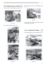
Page 50: ...f a hoover see 10 2 12 Clean the coffee grinder see 10 2 13 10 2 2 Drip tray cleaning Remove the tray and clean it carefully Fig 89 Fig 90 Use a hoover to eliminate the dirt inside the soluble product...

Page 51: ...cap and the drain hose again replace the tank inside the appliance 10 2 5 Stirrer channel cleaning Clean the stirrer channel carefully Fig 95 Fig 95 10 2 6 Coffee brewing unit cleaning Disconnect the...

Page 52: ...ows are aligned Otherwise align them using the provided key Loosen the fastening screws Fig 99 remove the coffee ground channel and wash it with lukewarm water Fig 100 Fig 101 10 2 7 Soluble product d...

Page 53: ...age the fan Carry out the inverse procedure to assemble the components and connect the dispensing hose correctly Fig 102 10 2 8 Dispensing outlet cleaning By shifting the locking levers remove the dis...

Page 54: ...outlet Fig 110 Fig 110 Assemble the dispensing outlet into the vending machine and check that the upper pin is not between the door wall and the microswitch tongue Fig 107 NO OK Fig 108 Every month al...

Page 55: ...ntainers cleaning To clean the coffee bean hopper you need to pull outwards the moving panel Fig 113 Dispense some coffee cups in order to empty the coffee grinder from coffee beans slide the containe...

Page 56: ...efore reassembling it To clean the sugar container you need to remove the elbow of sugar Fig 116 Fig 117 remove the container Fig 117 Fig 116 Fig 118 wash the container and dry it carefully before rea...

Page 57: ...122 10 2 10Dispensing arm cleaning Disconnect the hoses from the dispensing arm Fig 119 Fig 119 Fig 120 Fig 121 Disassemble the dispensing unit Fig 120 Lift the locking lever and remove the mobile dri...

Page 58: ...inverse procedure to assemble it Use a hoover to clean the refrigerating unit and the inside of the compartment Fig 124 Fig 124 10 2 13Coffee grinder cleaning Monthly clean the coffee grinder from an...

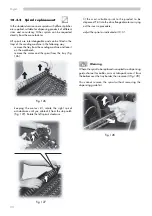
Page 59: ...als procedure described at 10 3 2 the replacement of the motors procedure described at 10 3 3 the modification of the layout of the trays procedure described at 10 3 4 10 3 1 Spiral adjustment The adj...

Page 60: ...and the spiral from the tray Fig 126 fit the most suitable spiral to the product to be dispensed Fit it into the drive flange of motor carrying out the inverse procedure adjust the spiral as indicate...

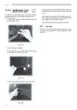
Page 61: ...tray from the vending machine and lean it on the workbench remove the motor and the spiral from the tray Fig 126 remove the spiral Fig 127 if present remove the dispensing guide Fig 128 remove the el...

Page 62: ...f the tray removing the front screw Fig 135 Fig 135 choose the desired seat in the vertical rod to reposition the guide channel Retighten the previously removed screw disassemble and reposition the le...

Page 63: ...he vending machine checks if a suitable external memory is present It this is the case the following message is displayed 10 4 Software updating The v m control program is in the flash memory inside t...

Page 64: ...AR 1 x SUGAR 2 xx SUGAR 3 xxxxx SUGAR 4 xxxxxxx DECAFFEINATED SELECTION x CAFFEE NOT AVAILABLE NOT AVAILABLE USE EXACT CHANGE NO LINK Error cedes 11 1 Messages during operation The table below shows a...

Page 65: ...ause of the blockage Add the cups see 7 4 Remove the cause that determined the block Check sensor efficiency Call the maintenance technician or contact the authorized service centers Switch off the ve...

Page 66: ...indicated in section 10 reassemble the components and close the doors raise and position the vending machine in the selected site as indicated at 5 2 12 2 Inactivity and storage When the vending mach...

Page 67: ...67 English...

Page 68: ...Cod 0875 971 Ed 02 10 03...

Reviews: