15
VORTEX CLOSED FLUME ASSEMBLY INSTRUCTIONS
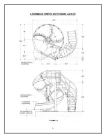
1. Assemble the four remaining Runway Section (2) pieces.
Order of assembly is important.
The
end of each runway section is labeled and must be assembled to the runway section with the same
label.
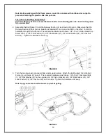
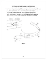
Assemble the lower two sections. They are labeled T1 on their mating ends. Fasten the sections
together using the screw hole locations located at the sides and the top of the Runway Section (2) as
shown in Figure K.
The hardware required for the two side locations is as follows: 3/8”-16 x 4” Button Head Cap Screw
S/S (
11), 3/8” Flat Washer S/S (18), 3/8” Flat Washer S/S (18), 3/8” Lock Washer S/S (22), 3/8” Hex
Nut S/S (23).
The hardware required for the top location is as follows: 3/8”-16 x 5” Button Head Cap Screw (12),
and a 3/8” Flat Washer S/S (18), 3/8” Flat Washer (18), 3/8” Lock Washer (22), 3/8” Hex Nut (23).
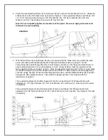
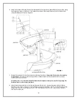
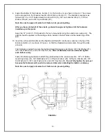
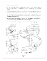
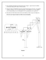
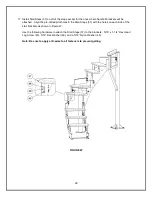
Follow the same procedure to finish assembling the remaining two sections. First, assemble the
Runway Sections (2) labeled T2, followed by the Runway Section (2) labeled T3.
Note: Be sure to apply anti-seize to all fasteners to prevent galling.
FIGURE K


