S.& A.S. OMEGA v1.0 User Manual Download Page 32

5. SD CARD 

5. SD CARD 

RETRIEVAL

RETRIEVAL

5. SD CARD RETRIEVAL

5. SD CARD RETRIEVAL
In order to retrieve Event or Time logs from OMGEA v1.2, a desktop application will be provided by S. & A. S. 
Ltd & the below steps shall be followed:
1. Run 

file 

“Log_Retrieve_Utility_windows.exe”.

2. 

Setup the application “Log_Retrieve_Utility_windows.exe”.

3. 

“S. &A. S - Log Retrieve Utility” will appear in the programs list. Send it to Desktop as shortcut.

5.1 DATA SAMPLING AND RETRIEVAL

5.1 DATA SAMPLING AND RETRIEVAL
1. 

With the OMEGA powered on and set to one of the four operating modes (Auto, Mains-Only or 

G1-Only or G2-Only mode), establish a USB Connection between the OMEGA and your PC.

2. 

Open the Desktop Application.
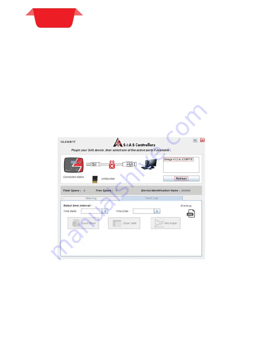
3. 

A Virtual COM port should appear as shown in the figure below (OMEGA 1.2 at: COM#). 

Otherwise, press the "Refresh" button or try to re-plugin the USB cable.
If the problem persists, consider using another PC USB port or replacing the USB Cable.

4. 

Select the port and enter the password.


32

Summary of Contents for OMEGA v1.0

Page 1: ... SEASIDE ROAD JIEH CHOUF T E L 9 6 1 7 9 9 6 3 3 3 2 L I N E S F A X 9 6 1 7 9 9 6 1 1 6 TECHNICALSUPPORT 961 71 996333E MAIL SUPPORT SASCONTROLLERS COM W W W S A S C O N T R O L L E R S C O M USER S MANUAL FOR H W VERSION 1 2 1 2a FOR S W VERSION 1 0 1925 AUTOMATIC TRANSFER SWITCH CONTROLLER AUTOMATIC TRANSFER SWITCH CONTROLLER OMEGA ATS ATSO OMEGA ATS ATSO ...

Page 2: ......

Page 3: ...SUBMENU 2 4 9 LCD DISPLAY SUBMENU 2 4 10 SD CARD SUBMENU 2 4 11 MENU MAPPING WITH PREVIOUS VERSION 2 5 PARAMETER DESCRIPTION 2 6TERMINAL DESCRIPTION 5 SD CARD 5 SD CARD RETRIEVAL RETRIEVAL 4 FIRMWARE 4 FIRMWARE UPGRADE UPGRADE 6 DIMENSIONS 6 DIMENSIONS TYPICAL WIRING TYPICAL WIRING DIAGRAM DIAGRAM 5 1 DATA SAMPLING AND RETRIEVAL 4 1 INSTALLING THE SAS DEVICE FIRMWARE UPGRADE SOFTWARE 4 2 INSTALLIN...

Page 4: ...play of the voltages and frequency on the three power sources Measurement and display of the current on the load side Measurement and display of the power on the load side All three supplies are monitored for over under voltage phase presence and sequence All three supplies are monitored for over under frequency Load side is monitored for over current when it is not supplied by the Mains Display o...

Page 5: ... is not mounted User interface 16 char alphanumeric LCD displays with 5 push buttons to select between opera ng modes New Graphical LCD Display with Easy access to all measurements in one page Easy access to the menu One dedicated push bu on to select between modes Four push bu ons to navigate between displayed pages Ethernet Interface Not Available Op onal Modbus Port Not Available Op onal SD Car...

Page 6: ...G1 is feeding the load and the current goes above the G1 Max Load for a G1 MaxLd del delay G2 is requested If G2 is feeding the load and the current goes below the G2 Min Load for a G2 MinLd del delay G1 is requested When the Mains is re established the power is switched back with a dead transfer time Transfer after a restoration delay Mains Rest and the genset is shut down after the elapse of the...

Page 7: ... and TR The ESC ESC push button is used to switch between the two display modes Statuses page that shows the status of each power source Display Display Notes Notes Refer to section 2 3 for the available status displayed Separate page for each power source showing the status contactor state scrolling voltages frequency currents and power in KW Display Display Notes Notes The ESC ESC push button is...

Page 8: ...enerator supply is within the acceptable limits the phases are all present and in the right sequence and the OK signal is ac ve Mains power source is absent When blinking it indicates that the Mains power source is detected but with no valid measurements or and wrong phase sequence When On it indicates that the Mains supply is within the acceptable limits the phases are all present and in the righ...

Page 9: ...F StF CG F Start Fail caused by Failure of Gx contactor StFailCGx F StF CGxF Start Fail caused by Absence of AC signals StFail NoAC StF NoAC Start Fail caused by High voltage StFail HiV StF HiV Start Fail caused by Low voltage StFail LoV StF LoV Start Fail caused by High frequency StFail HiF StF HiF Start Fail caused by Low frequency StFail LoF StF LoF Start Fail caused by wrong phase sequence StF...

Page 10: ...ed Disengaging Diseng Fault Display Abbreviation U lity contactor failure C U Fail CU Fail One of the three phase voltages goes above the over voltage limits set by OVolt L N for a delay of OVolt del Hi Voltage Hi Volt One of the three phase voltages goes below the under voltage limits set by UVolt L N for a delay of UVolt del Lo Voltage Lo Volt The frequency goes above the value set in Over Freq ...

Page 11: ...elow for 10 minutes without the need to re enter the password for every menu access While in the menu if no push buttons are pressed for 25 seconds or if the ESC button is pressed the system will automatically exit the menu While editing a parameter in the menu if no push buttons are pressed for 10 seconds or if the ESC button is pressed the system will automatically exit the edit mode While in th...

Page 12: ... Response Response delay N A 0 to 999 sec 5 sec Flt bypass Fault bypass delay N A 0 to 999 sec 15 sec Warm up Warming up delay N A 0 to Start Fail Transfer dead time 10 sec 10 sec Off delay Off delay Inst Type set to GG 0 to 999 sec 10 sec Transfer Transfer dead me delay N A 0 to Start Fail Warm up 10 sec 0 sec Cooling Cooling down delay N A 0 to 999 sec 30 sec Over Freq Over frequency N A N 10 Hz t...

Page 13: ...day N Saturday Gensets readiness on Saturday All Days Ready set to N Y Genset ready on Saturday N Weekly Ex Weekly Exercising N A N Y N Alternate hrs Alternate number of hours Omega Type set to ATS G1 Highest priority to G1 G2 Highest priority to G2 1 to 99 hours 4 hours Req Priority Request Priority Omega Type set to ATSO G1 Highest priority to G1 G2 Highest priority to G2 Ld MGG only Load depend...

Page 14: ...ITY SUBMENU What you see on the display Descrip on Visibility Condition Range Default Value Mains Rest Mains Restora on delay Inst Type set to MGG or MG 0 to 999 seconds 10 sec Over Freq Over frequency Inst Type set to MGG or MG N 10 Hz to 70 Hz 55 Hz OFreq del Over frequency delay Inst Type set to MGG or MG 0 to 999 seconds 2 sec Under Freq Under frequency Inst Type set to MGG or MG N 10 Hz to 70...

Page 15: ... 4 8 ETHERNET SUBMENU 2 4 8 ETHERNET SUBMENU What you see on the display Descrip on Visibility Condition Range Default Value Ethernet Ethernet feature Ethernet HW available N Ethernet disabled Y Ethernet enabled Y DHCP DHCP Ethernet set to Y N DHCP disabled Y DHCP enabled Y SITEID SITE ID Ethernet set to Y 6 Characters long XXXXXX IP ADDRESS IP ADDRESS Ethernet set to Y DHCP set to N N A 192 168 0...

Page 16: ...verFrq Hz Over Freq UTILITY SUBMENU U OvrFrq dly OFreq del UTILITY SUBMENU U UndrFrq Hz Under Freq UTILITY SUBMENU U UndrFrqdly UFreq del UTILITY SUBMENU U OverVolt V OVolt L N UTILITY SUBMENU U OvrVlt dly OVolt del UTILITY SUBMENU U UnderVolt V UVolt L N UTILITY SUBMENU U UndrVltdly UVolt del UTILITY SUBMENU G OverFrq Hz Over Freq GENSET SUBMENU G OvrFrq dly OFreq del GENSET SUBMENU G UndrFrq Hz ...

Page 17: ...tor For ATS the Alternate hrs parameter indicates the number of hours that a generator must run before the other generator is requested If set to G1 G1 is given priority and if set to G2 G2 is given priority The Weekly Ex parameter enables disables the weekly exerciser When enabled any generator that did not operate between Sunday and Friday would be started on Saturday at 8 00 am for half an hour...

Page 18: ...h Frequency 11 U lity Low Frequency 12 U lity Wrong Sequence G1 Status input register 30011 1 R 13 Engine Standby 14 Engine Ready 15 Engine Counting response delay 16 Engine Starting 17 Engine OK Wai ngAC 18 Engine Warming Up 19 Engine Engaging load 20 Engine Cooling down 21 Engine Shu ing down 22 Engine s Contactor Engaged 23 Engine Feeding Load 24 Engine Disengaging load 25 Engine OK Failure 26 ...

Page 19: ...tage in V G2 TN voltage input register 30030 1 R G2 phase T Neutral voltage in V G2 RS voltage input register 30031 1 R G2 phase R to phase S voltage in V G2 ST voltage input register 30032 1 R G2 phase S to phase T voltage in V G2 TR voltage input register 30033 1 R G2 phase T to phase R voltage in V U lity frequency input register 30034 1 R U lity frequency in Hz 10 format i e if this register v...

Page 20: ...t transformer on line S p1 35 LINE SM Line S Mains supply 30 CT R P2 Current transformer on line R p2 36 NOT USED Not used 31 CT R P1 Current transformer on line R p1 37 LINE RM Line R Mains supply CONNECTOR T ERMINAL P7 P8 38 N G1 Neutral G1 supply 44 N G2 Neutral G2 supply 39 LINE TG1 Line T G1 supply 45 LINE TG2 Line T G2 supply 40 NOT USED Not used 46 NOT USED Not used 41 LINE SG1 Line S G1 su...

Page 21: ...24Vdc Digital inputs ac va on logic Low ground Output relays rating 10A 250V ac1 AC inputs range L N 0 to 280Vac CT inputs range 0 to 5Amps Opera ng temperature 30 to 70 C User access Mode push bu on and four naviga on push bu ons Data sampling rate 1 2 samples sec Dimensions 208x160x40 IP IP20 once installed in panel unit is splash proof and can be installed outdoors as long as no direct sunlight...

Page 22: ... the programs list Send it to Desktop as shortcut 4 2 INSTALLING THE SAS DEVICE USB DRIVER 4 2 INSTALLING THE SAS DEVICE USB DRIVER 1 Plug in the USB cable to the SAS device before turning power on 2 Turn on power of the SAS device All the leds on the front starts blinking 4 2 1 DRIVER SETUP FOR WINDOWS VISTA WIN7 4 2 1 DRIVER SETUP FOR WINDOWS VISTA WIN7 The first SAS device plugged into the PC U...

Page 23: ...Select Search automatically for updates driver software 4 FIRMWARE 4 FIRMWARE UPGRADE UPGRADE 23 ...

Page 24: ...ected to the PC USB port will be installed automatically 4 2 2 DRIVER SETUP FOR WINDOWS XP 4 2 2 DRIVER SETUP FOR WINDOWS XP Each time New SAS Device is plugged into the PC USB port a Found New Hardware Wizard window appears Select Install the software automatically Recommended and click next Select Continue Anyway 4 FIRMWARE 4 FIRMWARE UPGRADE UPGRADE 24 ...

Page 25: ...E PROCESS Run SAS_PTool application The following window will appear prompting the user that the SAS board is detected on the USB port Click Open to choose the sas file that will be used to upgrade the firmware A Footnote will appear showing the file name the software version and its date Click upgrade 4 FIRMWARE 4 FIRMWARE UPGRADE UPGRADE 25 ...

Page 26: ...ow Once the upgrade is complete the footnote Firmware upgraded successfully will appear Then the SAS device firmware upgraded successfully and the SAS device will automatically run the new firmware 4 FIRMWARE 4 FIRMWARE UPGRADE UPGRADE 26 ...

Page 27: ...MWARE APPLICATION ON THE MOBILE In order to upgrade the firmware from your mobile follow the below steps 1 Search for the application SASPTool on Google play store and install it or follow the link below https play google com store search q SASPTool FIRMWARE UPGRADE PROCESS 2 Run SAS_PTool application from the mobile The below window appears showing all sas files already saved 4 FIRMWARE 4 FIRMWAR...

Page 28: ...ce on The following window will appear showing that a SAS Device is now connected 6 Click on the sas file that you need to download A POPUP POPUP window will appear showing the file name its description and its date 7 Click Yes The Download Will Start 4 FIRMWARE 4 FIRMWARE UPGRADE UPGRADE 28 ...

Page 29: ...sconnect the USB cable The user can now process with normal operation If you desire to delete any sas file from the mobile list press and hold on the filename until a POPUP POPUP window appears showing multiple choices and then click on Remove from list 4 FIRMWARE 4 FIRMWARE UPGRADE UPGRADE 29 ...

Page 30: ...Enter the username and the correspondent password to access your already registered account 3 A list of your OMEGA controllers appears see the figure below 4 Check Controller Ver and Eth Ver of the OMEGA to see if any upgrade is needed 5 To upgrade the OMEGA make sure the gensets are turned off and then click on the button Firmware Upgrade as shown in the image below 6 The user is prompted to ente...

Page 31: ...and its extension ICSP_OMEGA _online sas 10 Click Start Firmware upgrade Button A pop up window shows the description of both Firmwares Double check the description before confirming the start of the upgrade process 11 The Ethernet firmware and Controller firmware download will be started consecutively once finished a green symbol is displayed indicating that the upgrade process on the OMEGA itsel...

Page 32: ...list Send it to Desktop as shortcut 5 1 DATA SAMPLING AND RETRIEVAL 5 1 DATA SAMPLING AND RETRIEVAL 1 With the OMEGA powered on and set to one of the four operating modes Auto Mains Only or G1 Only or G2 Only mode establish a USB Connection between the OMEGA and your PC 2 Open the Desktop Application 3 A Virtual COM port should appear as shown in the figure below OMEGA 1 2 at COM Otherwise press t...

Page 33: ... entered password is valid make sure the SD CARD is considered Mounted and select the type required Time Log or Event Log then choose the Start End dates and press the Excel Sheet Button 6 Select the path and name for the Excel file to be exported 33 ...

Page 34: ...ve process should start and the progress will be indicated by an animated loader with the completed percentage 8 Wait until the loader disappears at this stage the progress is finished and you can find the exported file at the path specified in step 5 34 ...

Page 35: ...6 DIMENSIONS 6 DIMENSIONS TYPICAL WIRING TYPICAL WIRING DIAGRAM DIAGRAM 6 DIMENSIONS TYPICAL WIRING DIAGRAM DIMENSIONS DIMENSIONS TYPICAL WIRING DIAGRAM TYPICAL WIRING DIAGRAM 35 ...

Page 36: ...stallation Note 1 External contact supplied from the autostart of the genset Contact closed Genset is running ready to supply the load no need for warm up delay Contact open Genset has a fault or cannot supply the load Note 2 Should be connected to the remote control terminals of the autostart of the genset Contact closed Genset should start no need for response delay Contact open Genset should sh...

Page 37: ... CM F B P Note 1 External contact supplied from the autostart of the genset Contact closed Genset is running ready to supply the load no need for warm up delay Contact open Genset has a fault or cannot supply the load Note 2 Should be connected to the remote control terminals of the autostart of the genset Contact closed Genset should start no need for response delay Contact open Genset should shu...

Page 38: ... S Line T P1 P2 P1 P2 P1 P2 CTR P1 CTR P2 CTS P1 CTS P2 CTT P1 CTT P2 LINE R G2 LINE S G2 LINE T G2 G2 N R S T N R S T N G1 G2 LINE R G1 LINE S G1 LINE T G1 G1 N Current transformers installed on Load Side Main Supply Main N N LINE T M T LINE R M R LINE S M S 37 35 33 32 43 41 39 38 49 47 45 44 31 30 29 28 27 26 AC Inputs Not connected in MG installation Not connected in GG installation Connected ...

Page 39: ... R G A1 A2 CG Taken from output of CG1 CG2 Taken from output of CG1 CG2 FUSE LINE R G2 22 14 23 25 24 15 17 16 19 21 20 18 NOTE 2 NOTE 1 NOTE 1 ATS12a Sch Note 1 Used as an alarm output if fault exists on G1 or G2 in case contactors are used for the transfer switch Note 2 Used as an alarm output if utility is absent in case contactors are used for the transfer switch Note 3 For use with motorized ...

Page 40: ...G2 ATS12a Sch Not connected in MG installation Not connected in GG installation Connected only in MGG installation N Main MCB MCO G1 N G1 M ENG D ENG MCB MCO M M ENG D ENG MCB MCO G1 MCB MCO G2 MCB MCO G2 MCB MCO M OMEGA v1 2a Board FUSE LINE R M CM NOTE 4 C NOTE 3 CG2 NOTE 4 C NOTE 3 CM Eng CM D NO CM D NC CG2 Eng CG2 D NO CG2 D NC FUSE LINE R G1 CG1 NOTE 4 C NOTE 3 CG1 Eng CG1 D NO CG1 D NC FUSE...

Page 41: ...32 mm 208x160x32 mm 196x144x33 mm Panel cut out 68 5x68 5 mm 68 5x68 5 mm 184x139 mm 182x137 mm Number of Phases 1 Phase 1 Phase 1phase 3Phases 1phase 3Phases Digital Outputs 4 4 6 10 Digital Inputs 5 5 5 5 Analog Inputs 2 4 4 Voltage Measurement 1 L N 1 L N 3 L N 3L L 3 L N 3L L Frequency Measurement Current Measurement Power Measurement Energy Measurement Run hours counter Oil run hours counter ...

Page 42: ...own Battery alarm Dynamo fail alarm and shut down Low coolant level alarm and shut down Low fuel alarm and shut down Tank Empty alarm and shut down Automatic shutdown on fault condition Solid state short circuit protected outputs Galvanic isolation for utility and Genset AC inputs Oscilloscope Faults Logging Up to 10 faults Up to 15 faults Up to 100 faults 42 ...

Page 43: ... LT v1 0 Surf 1 2c EVENTS AND DATA LOGGING USB interface CAN Module J1939 Protocol Optional Ethernet Module RS485 Modbus Optional MicroSD Card SMS via GSM Module RS232 Interface On site Firmware Upgrade Remote Online Firmware Upgrade 43 ...

Page 44: ......

Reviews: