


3
English |
Original instructions
WARNING
Service and maintenance require extreme care and
NQRZOHGJHDQGVKRXOGEHSHUIRUPHGRQO\E\DTXDOL¿HG
service technician. For service and repair, contact an
authorised service centre. When servicing, use only
original manufacturer’s replacement parts, accessories,
and attachments.
Ŷ
Do not make adjustments and repairs not described in
this manual. For other repairs, contact an authorised
service centre.
Ŷ
Before performing any maintenance, stop the engine
and ensure the engine/choke lever is in the off position.
Ensure the engine and exhaust of the product has
cooled down. Failure to heed this warning could result
in serious personal injury or could damage the product.
WARNING
Protection switches or circuit breakers are vital for safety
and may only be replaced by an authorised service
centre.
Ŷ
Keep the product in a clean and dry environment where
it is not exposed to dust, dirt, moisture, or corrosive
vapours. Do not allow the cooling air slots in the
generator to become clogged with foreign material such
as leaves, and snow.
Ŷ
Do not use a garden hose to clean the product. Water
entering the fuel system or other internal parts of the
product can cause problems that will decrease the life
of the product.
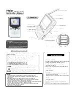
SYMBOLS ON THE PRODUCT
Do not expose to rain or use in
damp locations.
To reduce the risk of injury, the
user must read and understand the
operator’s manual before using the
product.
Precautions that involve your safety.
Always wear safety goggles or safety
glasses with side shields and, as
necessary, a full face shield when
operating this product.
Failure to use in dry conditions and
to observe safe practices can result
in electric shock.
Running the generator gives off
carbon monoxide, an odourless,
colourless, poison gas. Breathing
carbon monoxide can cause
nausea, fainting, or death.
Fuel and its vapours are extremely
ÀDPPDEOHDQGH[SORVLYH)LUHRU
explosion can cause severe burns
or death.
To reduce the risk of injury or
damage, avoid contact with any hot
surface.
Consult with local electrician
to determine the grounding
requirements before operation.
Fuel and its vapors are explosive and
can cause severe burns or death.
Turn the fuel valve to the on or off
position.
RUN
CHOKE
Turn the choke lever to the start or
run position.
93 dB
74 dB
Guaranteed sound pressure level is
74 dB.
Guaranteed sound power level is 93
dB.
Add lubricant
Do not twist the oil cap when adding
engine lubricant or when checking the
lubricant level.
After adding the lubricant or checking
the lubricant level, replace and ensure
that the oil cap is securely placed.
Gasoline fuel only.
Do not use diesel fuel.
MUFFLER
HOT
Hot muffler
Do not use the product indoors.
Only run the product outdoors.
Regulatory Compliance Mark (RCM).
Product meets applicable regulatory
requirements.
The following signal words and meanings are intended to
explain the levels of risk associated with the product.
DANGER
Indicates an imminently hazardous situation, which, if
not avoided, will result in death or serious injury.
WARNING
Indicates a potentially hazardous situation, which, if not
avoided, could result in death or serious injury.
CAUTION
Indicates a potentially hazardous situation, which, if not
avoided, may result in minor or moderate injury.
Summary of Contents for RGN3600B
Page 1: ...ORIGINAL INSTRUCTIONS Low Power Generating Set RGN3600B...
Page 4: ...Fig 4 Fig 5 Fig 6 11 8 9 6 10 Fig 7 Fig 8 16 15 13 12 17 14...
Page 5: ...Fig 9 7 13 12 14 Fig 10 2 Fig 11 20 19 18 21 Fig 12...
Page 6: ...Fig 13 Fig 15 Fig 16 Fig 17 Fig 14 22 28 26 27 29 24 25 23 30...
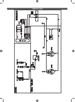
Page 21: ...WIRING DIAGRAM...
Page 22: ......
Page 23: ......