


9
English |
Original instructions
ETHANOL FUELS
CAUTION
Do not use E15 or E85 fuel (or fuel containing greater
than 10% ethanol) in the product. It is a violation of
federal law and will damage the product and void your
warranty.
Fuel system damage or performance problems resulting
from the use of an oxygenated fuel containing more than
the percentage of oxygenates stated below are not covered
under warranty.
Ethanol. Gasoline containing up to 10% ethanol by volume
(commonly referred to as E10) is acceptable. E15 and E85
are not.
AC OPERATION
Ŷ
Unplug all loads from the generator.
Ŷ
Switch the AC circuit breakers to the OFF (O) position.
Ŷ
Start the engine. Refer to "STARTING THE ENGINE"
section in this manual.
Ŷ
Switch the AC circuit breakers to the ON ( I ) position.
Ŷ
Plug in the appliance.
STARTING THE ENGINE
See figures 6-8
CAUTION
On a level surface with the engine off, check the lubricant
level before each use of the generator.
NOTE:
If location of generator is not level, the unit may not
start or may shut down during operation.
Ŷ
Turn the fuel valve to the ON position.
Ŷ
Move the choke lever to the START position.
NOTE:
If engine is warm, push the choke lever in to the
RUN position.
Ŷ
Put the engine switch in the ON ( I ) position.
Ŷ
Pull the recoil starting grip until the engine runs (a
maximum of 6 times).
NOTE:
Do not allow the grip to snap back after starting;
return it gently to its original place.
Ŷ
Allow the engine to run for 30 seconds, then move the
choke lever in to the RUN position.
STOPPING THE ENGINE
See figures 6-7
To stop the engine under normal operating conditions:
Ŷ
Remove any load from the generator.
Ŷ
Put the engine switch in the OFF ( O ) position.
Ŷ
Turn the fuel valve to the OFF position.
To stop the engine in an emergency situation:
Ŷ
Put the engine switch in the OFF ( O ) position.
WARNING
While operating and storing, keep at least 1 m of
clearance on all sides of the product, including overhead.
Allow a minimum of 30 minutes of “cool down” time
EHIRUH VHDW FUHDWHG E\ PXIÀHU DQG H[KDXVW
gases could be hot enough to cause serious burns and /
or ignite combustible objects.
USING THE GENERATOR
Connect devices to be powered by generator by following
the steps below:
Ŷ
Make sure the generator can supply enough continuous
(running) and surge (starting) watts for the items you
will power at the same time. See the Electrical section
for how to calculate total amount of power needed.
Ŷ
Start the generator with nothing connected.
Ŷ
Plug in and turn on the first load, preferably the largest
load (highest wattage) you have.
Ŷ
Permit the generator output to stabilise (engine runs
smoothly and attached device operates properly).
Ŷ
Plug in and turn on the next load.
Ŷ
Again, permit the generator to stabilise.
Ŷ
Repeat previous two steps for each additional load.
WARNING
Never add more loads than the generator capacity.
Take special care to consider surge loads in generator
capacity.
MOVING THE GENERATOR
See figure 15-17
Ŷ
Remove any load from the generator.
Ŷ
Turn engine switch OFF ( O ).
Ŷ
Close the fuel valve.
Ŷ
Make sure the engine and the exhaust of the product
has cooled down.
Ŷ
Unfold the generator frame handle.
Ŷ
Facing the side opposite the recoil starter, grasp the
frame handle firmly.
Ŷ
Lift the generator toward you until it balances on the
wheels.
Ŷ
Turn around and pull the product along behind you to
the desired location.
Ŷ
Lower the generator until it sits securely on a flat
surface.
HIGH ALTITUDE OPERATION
The product is not designed for high-altitude operation
(altitudes greater than 1,500 m above sea level). Operating
the product in higher altitudes may increase the engine’s
emissions, decrease fuel economy and performance and
reduce the generator life.
Summary of Contents for RGN3600B
Page 1: ...ORIGINAL INSTRUCTIONS Low Power Generating Set RGN3600B...
Page 4: ...Fig 4 Fig 5 Fig 6 11 8 9 6 10 Fig 7 Fig 8 16 15 13 12 17 14...
Page 5: ...Fig 9 7 13 12 14 Fig 10 2 Fig 11 20 19 18 21 Fig 12...
Page 6: ...Fig 13 Fig 15 Fig 16 Fig 17 Fig 14 22 28 26 27 29 24 25 23 30...
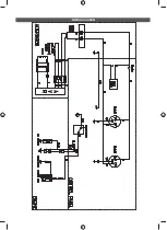
Page 21: ...WIRING DIAGRAM...
Page 22: ......
Page 23: ......


