background image

Page 8

KNOW YOUR ANGLE GRINDER

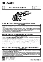
Before attempting to use your grinder, familiarize yourself
with all operating features and safety requirements.
See Figure 1.
Make sure all grinding wheels  and recommended accessories
are in accordance with listed specifications for this tool. For
example, do not use grinding wheels that are rated at less
than 11,000 RPM.

Guard

A protective guard has been provided on your grinder. It
deflects sparks and metal chips during use.

Heavy Duty Motor

Your angle grinder has a powerful motor with sufficient
power to handle tough grinding jobs that require heavy duty
performance.

Side Handle

The side handle provided, stabilizes your grinder and must
be used during all operations. In addition to maintaining safe
control during use, the side handle also provides convenient
ease of operation for the operator.

FEATURES

Spindle Lock Button

The spindle lock button secures the spindle so that only one
wrench is needed to change the grinding wheel.

Switch with Lock-on Feature

Your grinder has a conveniently located switch. It also has a
lock-on feature that allows the grinder to be locked in the on
position when continuous operation for extended periods of
time is required.

APPLICATIONS

(Use only for the purposes listed below)

Grinding metals.

Sanding wood or metal surfaces.

Wire brushing rusted or painted surfaces.

WARNING:

Do not allow familiarity with your grinder to make you
careless. Remember that a careless fraction of a second
is sufficient to inflict severe injury.

WARNING:

Your grinder should never be connected to power supply
when you are assembling parts, making adjustments,
installing or removing grinding wheels, or when not in use.
Disconnecting your grinder will prevent accidental starting
that could cause serious injury.

INSTALLING THE SIDE HANDLE

See Figure 2.

Unplug your grinder.

ASSEMBLY

a

aaa

aaaaaaa

a

a a a aaa

aaa

a

a

a

Fig. 1

SPINDLE

LOCK BUTTON

TRIGGER SWITCH

SIDE HANDLE

GUARD

GRINDING WHEEL

LOCK-ON

BUTTON

Fig. 2

GEAR

HOUSING

SIDE

HANDLE

Summary of Contents for AG450

Page 1: ...lly read through this entire operator s manual before using your new angle grinder Pay close attention to the Rules for Safe Operation Warnings and Cautions If you use your grinder properly and only f...

Page 2: ...ENTS a a a a a a a a AG450 ANGLE GRINDER TYPICAL APPLICATION WARNING Always use the guard that accompanied the grinder Comply with mounting and use instructions and warnings found in the manual for th...

Page 3: ...ower tool is double insulated This means you are separated from the tool s electrical system by two complete sets of electrical insulation This extra layer of insulation is intended to protect the use...

Page 4: ...misalignment or binding of moving parts breakage of parts and any other condi tion that may affect the tool s operation If dam aged have the tool serviced before using Many accidents are caused by po...

Page 5: ...ting Inspect for and remove all foreign objects from workpiece before grinding Following this rule will reduce the risk of serious personal injury Use only accessories that are recommended by the manu...

Page 6: ...s Double Insulated Construction tools Revolutions strokes surface speed orbits etc per minute Indicates danger warning or caution It means attention Your safety is involved Important Some of the follo...

Page 7: ...power supply that is 120 volts 60Hz AC only normal household current Do not operate this tool on direct current DC A substantial voltage drop will cause a loss of power and the motor will overheat If...

Page 8: ...cures the spindle so that only one wrench is needed to change the grinding wheel Switch with Lock on Feature Your grinder has a conveniently located switch It also has a lock on feature that allows th...

Page 9: ...the same direction as in prior use Failure to heed this warning can result in bristle breaking and extreme vibration of the wire wheel brush that could result in serious personal injury WARNING Failu...

Page 10: ...nd loose particles thrown from the grinding wheel would be directed toward the operator Always place the guard in the correct location as shown in figures 4 and 5 WARNING Always wear safety glasses an...

Page 11: ...ury WARNING Never use your grinder without wearing eye protection Following this rule will reduce the risk of serious personal injury Fig 7 WARNING Inspect wire wheel brush before each use Never use o...

Page 12: ...the clamp screw until the guard can be removed from the bearing cap Place the new guard on the shoulder of the bearing cap See Figure 9 Note If the new guard will not fit loosen the clamp screw until...

Page 13: ...ve dirt carbon dust etc WARNING Do not at any time let brake fluids gasoline petroleum based products penetrating oils etc come in contact with plastic parts They contain chemicals that can damage wea...

Page 14: ...r exposed wires and cut or worn insulation Ampere rating on tool data plate 0 2 0 2 1 3 4 3 5 5 0 5 1 7 0 7 1 12 0 12 1 16 0 Cord Length Wire Size A W G 25 16 16 16 16 14 14 50 16 16 16 14 14 12 100 1...

Reviews: