


24
MOBILE AND WORKSHOP SERIES OPERATION MANUAL
October 2018 | Version: v1-0
MAINTENANCE
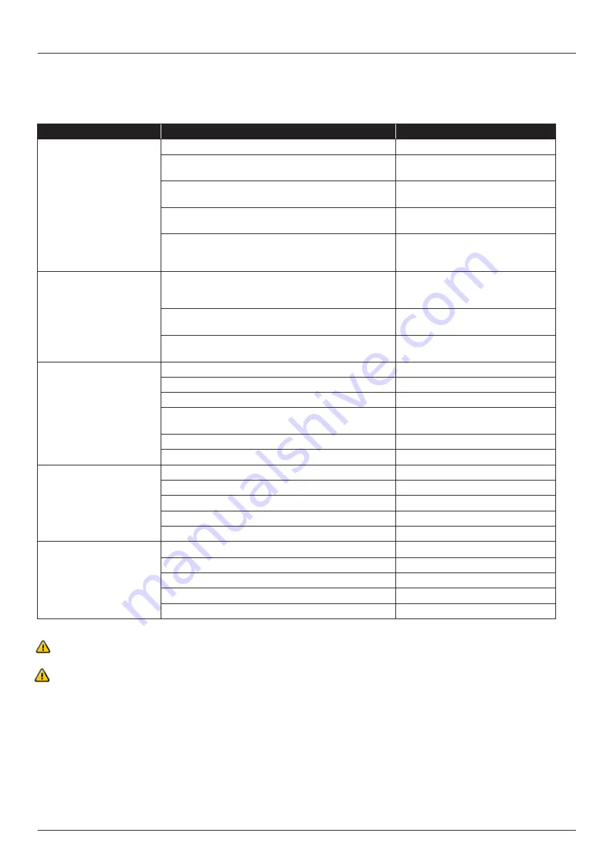
Problem
Possible Cause
Solution
Machine doesn’t start
1.
No power is supplied
Check the main power source
2.
Open circuit or poor connection of the power circuit
Check the fuse is broken or overload
relay is actuated (shut-off)
3.
The interlock guard is opened
Check the interlock guard is closed
completely
4.
Motor fault, magnetic contactor, or other component Please call a qualified service
electrician
5.
The Emergency stop button is actuated
Check the hazard is eliminated, then
reset the EMS button and power ON
again
Machine starts but stops
immediately, causing the
motor protector to actuate.
1.
Voltage drop
Correct the voltage to the rated
voltage, or check the power cable
meets the standard requirements
2.
A 50Hz model is operated at 60Hz
Check the nameplate and/or call a
qualified service electrician
3.
Abnormal motor noises
Repair the motor or replace
(call a qualified electrician)
Motor runs but no piston
movement
1.
Motor running in wrong direction
Check the 3 phase connection
2.
Low oil level
Fill or top up oil
3.
Fuse blown
Replace
4.
Valve not working
Check valves are free and solenoids
are working
5.
Dial broken
Check and replace
6.
Pump or coupling broken
Check and replace
Insufficient crimping force
1.
Insufficient lubrication
Clean and lubricate the dies
2.
Low oil level
Check and top up
3.
Pressure relief valve stuck
Check and clean
4.
Leaking pump or pressure pipe
Check, tighten or replace
Coupling between pump and motor slipping
Check and replace
Crimp diameter varies
1.
Insufficient lubrication Clean and lubricate the dies
Clean and lubricate the dies
2.
Set value changed Check and rectify
Check and rectify
3.
Dial knob loose Check, calibrate tighten
Check, calibrate tighten
4.
Dial loose or broken Check and tighten, replace
Check and tighten, replace
5.
Valve sticking Check and clean
Check and clean
Troubleshooting is to be carried out by a serviceman.
If the above measures don’t help or the machine has other problems contact your RYCO representative. If you need to contact the
RYCO or the distributor about the operating or service-problems, remember to give your crimping machine’s serial number.
TROUBLESHOOTING