


22
MOBILE AND WORKSHOP SERIES OPERATION MANUAL
October 2018 | Version: v1-0
Calibration
CALIBRATION
SPECIFICATIONS
When the machine is consistently crimping outside the set size then a re-calibration is required.
To check the calibration perform the following.
1.
Enter a zero (0) crimp size on the digital pad.
2.
Manually close the crimp head without dies fitted.
3.
Measure the diameter of the master die when fully closed.
RY20C and RY32C should be 99.0 mm ID
4.
Record any difference between the expected and measured dimension.
5.
The difference is the adjustment required to calibrate the machine.
Example:
For the RY32C, we have a measured closed master die diameter of 101.2 mm.
The expected dimension is 99.0 mm a difference of 2.2 mm. 101.2 – 99 = 2.2
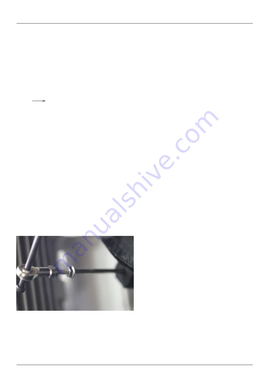
To make the correction perform the following.
To adjust the calibration, the length of the adjustment screw on the potentiometer need to be altered.
If the master die measures larger than the expected dimension, the screw must be made shorter (turn clockwise).
If the master die measures smaller than the expected, the screw must be made longer (turn counter-clockwise).
The difference in dimension (2.2mm) is multiplied by 3 to determine the change in screw length required.
Example:
2.2 x 3 = 6.6 mm, our measured dimension was larger than expected (101.2 mm)
Undo the lock nuts and turn the adjusting screw clockwise to shorten the length by 6.6 mm
Tighten the lock nuts and open the master dies.
Repeat the measuring process to ensure the expected dimensions are now correct.