REVT-05ERV 33
8. For troubleshooting purposes, an ignition attempt
after lockout may be re-established manually by
moving the thermostat switch to
"OFF"
and then
return to
"HEAT"
position
9. When the warm-up period expires, modulation of the
system is handed over to the Building Management
System.
10. If the building controller is providing an analog signal
between 2.0 and 10.0 vdc to the SC30 Control,
the system will modulate from 20 to 100% of the
modulating side input (ST1 LED light on).
11. As the call for heat continues, stage 2 comes on (ST2
LED light on) and, simultaneously, stage 1 decreases
to minimum output.
12. If the Building Management System continues to
call for heat, stage 1 continues to increase rate until
system is running at 100% capacity.
13.
When the building thermostat is satisfied and the
demand for heat ends, the Gas Valve is de-energized
immediately and the Combustion Air Inducer switches
to high speed for a 30-second post-purge period.
Limit Controls
- Limit controls are factory-set and are not
adjustable.
Heating Adjustment
- Main burners are factory-set and
do not require adjustment.
XVI - ROUTINE MAINTENANCE
CAUTION
Label all wires prior to disconnection when servicing
controls. Wiring errors can cause improper and
dangerous operation. Verify proper operation after
servicing.
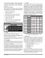
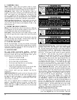
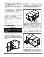
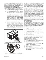
FIGURE 26- MESH FILTER INSTALLATION
A. INTAKE HOOD MESH FILTER(S)
The aluminum mesh filter(s) located in the standard
Fresh Air Hood (
See Figure 26
) must be cleaned on a
regular basis for best efficiency (not applicable for units
with EME). The frequency depends on cleanliness of the
incoming air.
B. SUPPLY AND RETURN AIR FILTERS
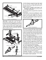
Supply Air Filters
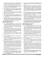
- Located upstream of the Enthalpy
Wheel as shown in
Figure 27
. Should be checked
regularly and cleaned or replaced. Again the frequency
depends on cleanliness of the incoming air. It is important
that the wheel, and tempering coil (if present) remain
clean to maintain desired airflow and efficiency.
MESH FILTER
FILTER RETAINER
FIGURE 27 - SUPPLY AIR FILTER LOCATION
FILTER SPACER
SUPPLY FILTER
SUPPLY FILTER ACCESS DOOR
EXHAUST AIR HOOD
OUTDOOR AIR HOOD
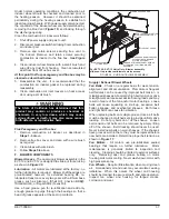
Return Air Filters
- Similar to the Supply Air Filters the
Return (or exhaust) Air Filters are located upstream of the
Enthalpy Wheel and are also shown in
Figure 28
. Should
also be checked regularly and cleaned or replaced. The
frequency depends on cleanliness of the return air, which
could vary considerably either way from that of the Supply
Air Filters. This is a function of the environment and
processes performed in the conditioned space. Like the
supply filters, maintaining the desired airflow and wheel
efficiency is directly dependent upon maintaining clean
filters.
FIGURE 28 - EXHAUST AIR FILTER LOCATION
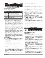
Filter Size and Quantity
-
Table 10
on
Page 34
gives the
number and size filter for each unit model. Note that the
supply and return filters are identical within a given unit.
EXHAUST FILTER ACCESS DOOR
EXHAUST AIR HOOD
EXHAUST FILTER
OUTDOOR AIR HOOD
Summary of Contents for ENERVENT+ EVT-09 Series
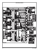
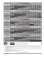
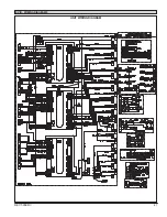
Page 30: ...30 REVT 05ERV UNIT WIRING DIAGRAM ...
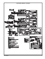
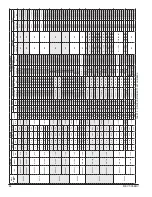
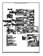
Page 31: ...REVT 05ERV 31 UNIT WIRING DIAGRAM CONTINUED ...
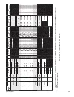
Page 47: ...REVT 05ERV 47 UNIT WIRING DIAGRAM XVIII WIRING DIAGRAMS ...
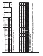
Page 48: ...48 REVT 05ERV UNIT WIRING DIAGRAM CONTINUED ...
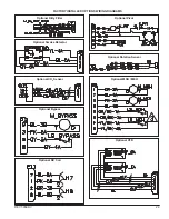
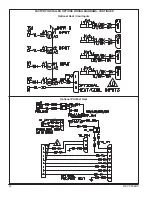
Page 50: ...50 REVT 05ERV Optional Heat Cool Inputs Optional Pre Post Heat ...
Page 57: ...REVT 05ERV 57 DIAGRAM 15 5 1 MODULATION GAS POST HEAT DIAGRAM 14 2 STAGE GAS POST HEAT ...

