REVT-05ERV 23
This mode will only engage if "Cooling Control Mode",
"Low Ambient Control Mode", "Smoke Control Mode",
"Post Heat Control Mode", "Pre-Heat Control Mode",
"Start Stop Jog Control Mode" or "CO
2
Control Mode" is
not active.
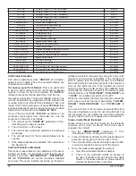
Failure Alarms (Standard)
Failure alarms are an indication for the user if something
goes wrong with the unit. All the alarms are Bacnet
exposed and can be monitored with BAS or Display panel.
1. Supply Air Fan Failure Alarm.
2. Exhaust Air Fan Failure Alarm.
3. Wheel Failure Alarm.
4.
Motorized Outside Air Damper Failure Alarm.
5.
Motorized Exhaust Air Damper Failure Alarm.
6. Return Air Dirty Filter Alarm.
7. Outside Air Dirty Filter Alarm.
8. Bypass Failure Alarm.
9. Supply Air Flow Set Point Out Of Range Alarm.
10. Exhaust Air Flow Set Point Out Of Range Alarm.
11. CO
2
Set Point Out Of Range Alarm.
WARNING
Electric shock hazard. Can cause injury
or death. Do not use this unit if any part
has been under water. Immediately call
a qualified service technician to inspect
the unit and to replace any part of the
control system and any gas control
which has been under water.
XV - UNIT STARTUP
A. WIRING
Before starting the Unit take the time to check all field
wiring to make sure it is securely connected.
Make sure that plugs for the OA and EA damper proving
switches are securely connected to the switches or the
jumpers if this option wasn't chosen.
On units with gas post heat make sure the Supply Air
Temp sensor is inserted into the supply duct 6'-10' from
the furnace outlet.
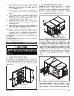
B. FAN WHEELS
Before applying electrical power rotate the blower wheels
by hand to assure that they turn freely and do not rub the
inlet orifice. If any binding occurs, check for damage or
foreign objects in the housing.
Upon applying power make certain that both fan wheels
are rotating in the required direction. Direction of rotation
must conform to the Rotation Sticker affixed to the outside
of the blower housing. A further visual indicator is whether
it rotates in the same direction as the blade curvature. All
ERV blowers have forward curved wheels. If rotation is in
the wrong direction, it can be reversed by interchanging
any two of the three field-installed electrical leads.
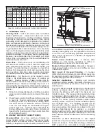
C. FAN RPM
The adjustable sheave on both the supply and the
exhaust blowers are factory set to the mid-range rpm
for the selected drive kit.
Refer to Section XII, Blower
Operation
, for instructions on changing blower RPM
and proper sheave alignment and belt tension. Before
powering the blower all access doors, other than the unit
Control Box, must be closed and the ductwork in place to
avoid overloading the motor. Check the motor amperage
reading against the motor nameplate to assure that it is
operating below the FLA rating. A further limitation is
the maximum operating RPM of the blower wheel listed
in
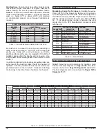
Table 6
. All Enervent blowers have a Class II rating
except for EVT-09, for which Class II are neither available
nor required for that blower model.
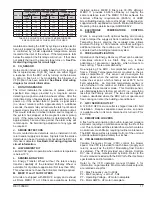
UNIT
LOCATION BLOWER MODEL
MAXIMUM RPM
DIA. x WIDTH
CLASS I CLASS II
EVT-09
Supply
A9 x 4AT
5200
NA
Exhaust
EVT-19
Supply
A10 x 6A
-
2488
Exhaust
EVT-28
Supply
A12 x 6A
A12 x 9A
-
-
2089
2058
Exhaust
EVT-36
Supply
A12 x 9A
A12 x 12A
-
-
2058
2091
*
Exhaust
EVT-46
Supply
A15 x 11A
-
1714
Exhaust
EVT-62
Supply
A15 x 11A
A18 x 13A
-
-
1714
1478
Exhaust
EVT-74
Supply
A18 x 13A
A18 x 18A
-
-
1478
1501
*
Exhaust
EVT-88
Supply
A18 x 13A
A18 x 18A
-
-
1475
1501
*
Exhaust
EVT-10
Supply
A20 x 9H (2)
A20 x 20H
NA
NA
1278
1278
Exhaust
EVT-12
Supply
A20 x 9H (2)
A20 x 20H
NA
NA
1278
1278
Exhaust
* Blower wheel is braced to obtain maximum Class II limit.
TABLE 6 - MAXIMUM BLOWER RPM
D. VIBRATION
Rubber vibration isolators are standard on all Enervent
blowers, which will eliminate most vibration and resulting
noise. However, if excessive vibration is present during
initial start-up it must be addressed immediately; for it
could result in major problems, such as structural or
component failure, immediately or in the near future. There
are numerous causes, but some of the most common are:
1. Blower wheel imbalance
2. Drive pulley imbalance or misalignment
3. Incorrect belt tension
4. Faulty belts
5. Bearing misalignment
6. Faulty belts
7. Loose fasteners
Many of these conditions can be discovered by careful
observation, if not, a qualified technician using vibration
analysis equipment should be consulted. If the problem
is blower wheel imbalance, it can be rebalanced in-place
by a technician with the proper equipment.
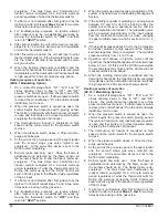
Summary of Contents for ENERVENT+ EVT-09 Series
Page 30: ...30 REVT 05ERV UNIT WIRING DIAGRAM ...
Page 31: ...REVT 05ERV 31 UNIT WIRING DIAGRAM CONTINUED ...
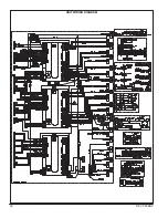
Page 47: ...REVT 05ERV 47 UNIT WIRING DIAGRAM XVIII WIRING DIAGRAMS ...
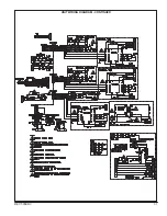
Page 48: ...48 REVT 05ERV UNIT WIRING DIAGRAM CONTINUED ...
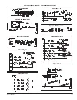
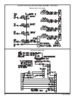
Page 50: ...50 REVT 05ERV Optional Heat Cool Inputs Optional Pre Post Heat ...
Page 57: ...REVT 05ERV 57 DIAGRAM 15 5 1 MODULATION GAS POST HEAT DIAGRAM 14 2 STAGE GAS POST HEAT ...


