14 REVT-05ERV
FIGURE 15 - TYPICAL CONTROLS LAYOUT
INPUT/OUTPUT
EXPANSION #1
WHEEL CONTACTOR
POWER DISCONNECT
FAC CONTROLLER
INPUT/OUTPUT
EXPANSION #2
CONTROLLER RELAYS
TRANSFORMERS
BMS CONNECTION
TERMINAL STRIP
XII - BLOWER OPERATION
A. 3 PH VOLTAGE PHASING
Three phase blower motors must be phased sequentially
to ensure correct rotation and operation. Motors are
wired in phase at the factory. Check for proper blower
wheel rotation by momentarily energizing blower demand
at the thermostat. Correct rotation is determined by
observing the wheel from the drive side and should match
the rotation decal affixed to the fan housing. If rotation is
not correct, direction can be reversed by interchanging
any two of the three field-installed leads in the base unit
control box. Make certain the connections are tight. Do
not reverse wires at blower contactor.
B. SPEED SETTING
All drives are factory set at mid-range.
1.
Determine Required RPM
- Starting with desired
supply side (outdoor air) CFM use
Chart 1
on
Page 40
to determine the internal static pressure (ISP) drop for
each option. Total these values and add the external
static pressure (ESP), then refer to
Chart 2
on
Pages
41-43
. Using this total SP (ISP + ESP) value, along
with the desired CFM, determine the RPM and BHP
required at that operating point. Adjust the blower
RPM by opening or closing the motor pulley. Loosen
the Allen screw and turn adjustable pulley clockwise
to increase RPM and counterclockwise to decrease
RPM.
Repeat this process for the return (exhaust) side to
determine the RPM and BHP requirements for that blower.
C. PULLEY ALIGNMENT
All Pulleys are laser aligned in the factory during
production, movement of the pulleys is possible however
if the set screws weren’t properly torqued down during
adjustment. Make sure blower and motor pulleys are
aligned as shown in
Figure 16
before commissioning is
complete.
D. BELT ADJUSTMENT
Maximum belt life can be obtained only if proper pulley
alignment and belt tension are maintained. Tighten new
belts after 24-48 hours of operation. This is necessary
to allow for belt stretch and for belts to seat into grooves.
1. Loosen four nuts securing blower motor to adjustable
base. To increase belt tension turn motor mount
adjustment screw counterclockwise. Turn adjustment
screw clockwise to decrease belt tension.
2. Check belt tension as follows:
a. Measure center distance (CD) between blower
and motor shafts as noted in
Figure 17
.
b. Apply force perpendicular to CD line with enough
pressure to deflect belt
1/64
inch per inch (1.5 mm
per 100 mm) of CD. Example: Deflection for a
CD of 24 inches would be
24/64
inch, or
3/8
inch.
c.
Measure belt deflection force. For a used belt,
the deflection force should be 5 lbs (35 kPa).
A new belt deflection force should be 7 lbs (48
kPa). A force below these values indicates an
under tensioned belt and a force above, an over
tensioned belt.
Summary of Contents for ENERVENT+ EVT-09 Series
Page 30: ...30 REVT 05ERV UNIT WIRING DIAGRAM ...
Page 31: ...REVT 05ERV 31 UNIT WIRING DIAGRAM CONTINUED ...
Page 47: ...REVT 05ERV 47 UNIT WIRING DIAGRAM XVIII WIRING DIAGRAMS ...
Page 48: ...48 REVT 05ERV UNIT WIRING DIAGRAM CONTINUED ...
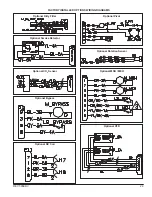
Page 50: ...50 REVT 05ERV Optional Heat Cool Inputs Optional Pre Post Heat ...
Page 57: ...REVT 05ERV 57 DIAGRAM 15 5 1 MODULATION GAS POST HEAT DIAGRAM 14 2 STAGE GAS POST HEAT ...


