background image

Installation Preparation

22

CineWall™ Installer/Integrator Manual

PRE

L

IMINAR

Y

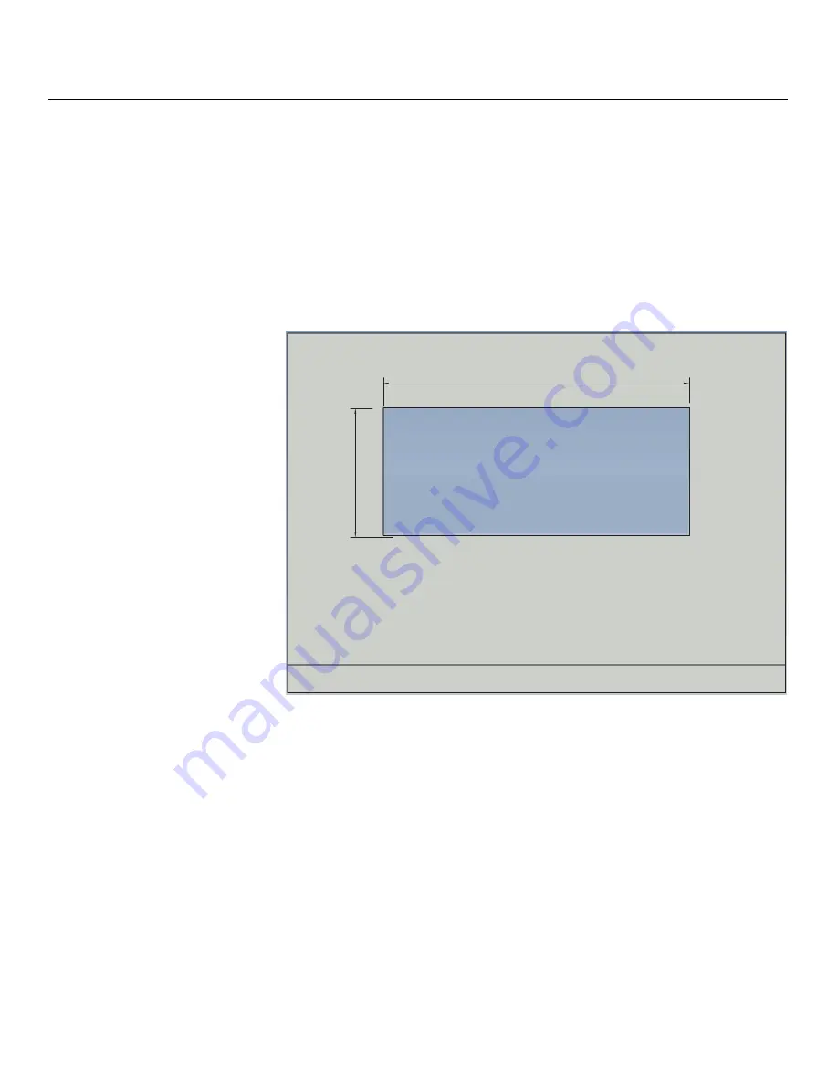
Create wall opening: 

1.

Locate the screen center based on the desired screen height.

2.

From this point, measure/mark 44.375 inches to the left and to the right and 19.25 
inches above and below. 

3.

Using a laser level, determine and mark the locations of the opening corners.

4.

Double-check your mea

s

urement

s

“Measure twice, cut once” is always a great 

rule of thumb to follow. 

5.

Using the marks as a guide, cut a rectangular opening 88.75 inches wide and 38.5 
inches tall. 

38.500"

(977.9 mm)

88.750" (2254.3 mm)

Summary of Contents for CineWall CW-95DHD

Page 1: ...CineWall CW 95DHD Full HD 2 35 1 In Wall Display and Digital High Definition DHD Controller Scaler Processor INSTALLER INTEGRATOR MANUAL...

Page 2: ...s manual may be reproduced by any mechanical electronic or other means in any form without prior written permission of Runco The trademarks reproduced in this Runco Owner s Manual and used on the Runc...

Page 3: ...cified by the manufacturer or sold with the apparatus When a cart is used use caution when moving the cart apparatus to avoid injury from tip over 13 Unplug this apparatus during lightning storms or w...

Page 4: ...Radio Frequency Electromagnetic Field Immunity Test EN 61000 4 4 Electromagnetic compatibility EMC Part 4 Testing and measurement techniques Section 4 Electrical fast transient burst immunity test EN...

Page 5: ...mits for a Class B digital device pursuant to Part 15 of the FCC Rules These limits are designed to provide reasonable protection against harmful interference in a residential installation This equipm...

Page 6: ...ot be treated as household waste when you wish to dispose of it Instead it should be handed over to an applicable collection point for the recycling of electrical and electronic equipment By ensuring...

Page 7: ...Benefits 4 Parts List 4 Required Personnel Tools and Materials 4 2 System Description 5 Chassis Assembly 5 Input Connectors and LEDs 6 Screen Assembly 6 Chassis Installation Brackets 7 Other System C...

Page 8: ...ponents to the DHD Controller 38 RS 232 Controller Connection 43 Connecting 12 volt Trigger Outputs to External Equipment 44 Connecting an External IR Receiver to the DHD Controller 45 Installing Batt...

Page 9: ...Maintain Lamp Life 76 Filter Replacement 76 Determining a Changing Schedule 76 Removing the Air Filter 77 Troubleshooting Tips 77 Status LEDs 77 Isolating Faulty Parts 78 7 Serial Communications 81 R...

Page 10: ...Table of Contents x CineWall Installer Integrator Manual P R E L I M I N A R Y Notes...

Page 11: ...Video Source Connections 39 4 7 RGBHV Source Connections 40 4 8 SCART RGBS Source Connections 41 4 9 S Video and Composite Video Source Connections 42 4 10 RS 232 Control System Connection 43 4 11 Co...

Page 12: ...List of Figures xii CineWall Installer Integrator Manual P R E L I M I N A R Y Notes...

Page 13: ...omes your comments about this manual Send them to techpub runco com Textual and Graphic Conventions Text Conventions The following conventions are used in this manual in order to clarify the informati...

Page 14: ...alert users that a given action or omitted action can degrade performance or cause a malfunction WARNINGS appear when a given action or omitted action can result in damage to the equipment or possibl...

Page 15: ...to achieve the highest level of image fidelity but it also enhances standard definition digital and NTSC content to near high definition quality The CineWall features Runco s SuperOnyx DMD chipset wi...

Page 16: ...n Assembly Controller DHD Controller Remote Control Unit and two 2 AAA size batteries Setup Remote Control Unit and two 2 AAA size batteries Two 2 AC Power Cords North America 1 83 meters 6 0 feet Com...

Page 17: ...embly contains all of the active components described below A fold mirror mounted at the rear of the chassis reflects light from the display engine Several sets of handles are provided on the chassis...

Page 18: ...e components associated with the screen which is attached on the outer side of the installation wall The Screen Assembly is packaged separately from the Chassis Assembly to facilitate unpacking and in...

Page 19: ...these can be screwed into the wall opening with sheet rock screws Top Flange The top flange locks the top of the chassis into position and stops the rotation of the chassis as it is being installed A...

Page 20: ...e cover is open Air Filter As mentioned above the air filter is installed in the plenum at the bottom center of the chassis This filter can be accessed and replaced by a service person by opening the...

Page 21: ...Composite Video 6 DOWN BUTTON Use to direct select aspect ratios or move the menu cursor down in the OSD When no menu is present on screen this button toggles through the different aspect ratios in t...

Page 22: ...dard USB Series B connection to a personal computer For future use 5 HDMI 1 HDMI 2 Digital HDCP compliant digital video inputs for connecting an HDMI or DVI source 6 HD1 HD2 5 x Analog BNCs Two inputs...

Page 23: ...nector for interfacing with a PC or automation control system Currently only RS 232 interface is supported 12 MAIN AC FUSE This is the main AC input fuse 5mm x 20mm 500 mA 250V slow blow 13 MAIN POWER...

Page 24: ...Cinema Native Likewise the LEFT and RIGHT buttons toggle through the different source inputs in this order LEFT Button HDMI 2 HDMI 1 SCART HD 2 HD 1 Component S Video 2 S Video 1 Composite Video RIGHT...

Page 25: ...masked SVC Selects the Virtual Cinema aspect ratio which enlarges a 16 9 image horizontally in a NON linear fashion to fit 2 35 1 full screen display 11 S VID 1 4 S VID 2 5 S Video Press to select an...

Page 26: ...System Description 14 CineWall Installer Integrator Manual P R E L I M I N A R Y Notes...

Page 27: ...CineWall is designed for installation into a dedicated framed structurally capable wall with at least 32 50 inches 826 mm of distance between the user viewable surface of this wall and anything immed...

Page 28: ...power cord ensure that it is a UL or CSA approved three conductor 18 AWG or heavier shielded cord rated at 10 amps minimum Site Access The CineWall is shipped in two containers one for the screen ass...

Page 29: ...ee ATSC prescribed tolerances According to the ATSC the sound program should never lead the video program by more than 15 milliseconds and should never lag behind the video program by more than 45 mil...

Page 30: ...es of these include slide projectors speakers power amplifiers and elevators Handle the unit carefully when installing or carrying it Use the built in handles DO NOT touch or hold the screen face Set...

Page 31: ...As you unpack each container check all parts against the shipping documents The CineWall is protected in the shipping containers Unpack them carefully inspecting the chassis and screen for scratches d...

Page 32: ...tainer and sliding the screen out of the box 6 Unpack the chassis hardware and verify that you have received all of the parts listed and shown below Item Number Description Quantity 1 Top Flange 1 2 L...

Page 33: ...heater for a CineWall installation Throughout these instructions the following typical conditions are assumed Wall thickness 3 inches 76 2 mm minimum 7 inches 177 8 mm maximum Stud spacing 24 inches 6...

Page 34: ...asure mark 44 375 inches to the left and to the right and 19 25 inches above and below 3 Using a laser level determine and mark the locations of the opening corners 4 Double check your measurements Me...

Page 35: ...Installation Preparation CineWall Installer Integrator Manual 23 P R E L I M I N A R Y 6 Frame the wall opening in a manner similar to this example 38 500 977 9 mm 88 750 2254 3 mm...

Page 36: ...Installation Preparation 24 CineWall Installer Integrator Manual P R E L I M I N A R Y Notes...

Page 37: ...ower switch on CineWall to ON Close screen Press ON on CineWall Setup remote control to turn on display 33 6 Align image corners with screen corners 34 7 Power down the CineWall Press OFF on CineWall...

Page 38: ...Then install the Left and Right Bottom Brackets the ones with the latches on them at the bottom corners of the chassis and install the Left Center and Right Center Bottom Brackets in the two intermed...

Page 39: ...to come to rest on the bottom of the wall opening Then rotate the chassis into the opening until the top flange makes contact with the top of the opening Secure Chassis to Wall Once the chassis is cor...

Page 40: ...as shown 2 Engage the slot at the top of the spacing tool with the hinge barrel on the Top Flange Ensure that the spacing tool is perpendicular to the top and bottom of the wall opening 3 Using wood...

Page 41: ...frame 6 Secure the Bottom Center Light Block Strut Catch to the opening frame between the two Center Bottom Brackets 7 Install the other Bottom Light Blocks left left center right center right as sho...

Page 42: ...he hinge on the top flange of the Chassis Assembly via six hooks along the top of the frame Two latches at the bottom of the frame secure the screen in the closed position A strut at the bottom of the...

Page 43: ...Integrator Manual 31 P R E L I M I N A R Y To install the screen 1 Remove the Spacing Tool used to install the chassis see page 28 2 With the help of your assistant s lift the screen and position it i...

Page 44: ...CineWall Installer Integrator Manual P R E L I M I N A R Y 3 Use the hooks to hang the frame on the hinge at the top of the chassis 4 Use the strut at the bottom of the frame to prop the screen in th...

Page 45: ...ll to AC Power Plug the female end of the power cord into the AC receptacle on the right side of the CineWall display engine next to the power switch Then connect the other end to your AC power source...

Page 46: ...rn shows all the pixels in the optical engine 7 Highlight Adjust Corners in the Image Alignment menu and press ENTER or 8 Use the and buttons to precisely position the upper left corner of the display...

Page 47: ...troller s if present and AC power When connecting your equipment Turn off all equipment before making any connections Use the correct signal cables for each source Ensure that the cables are securely...

Page 48: ...he sections that follow Figure 4 3 Connecting the CineWall to the DHD Controller Fan System Fan DMD Fan Lamp Ballast Status Engine Status Lamp Saver Serial Cmd Serial Data Remote IR Lamp Source Ready...

Page 49: ...232 input on the CineWall Use a cable with an RJ11 plug at the DHD Controller end and an RJ 45 plug at the CineWall end The CineWall accessory kit includes such a cable If you make your own cable it m...

Page 50: ...4 5 Figure 4 5 HDMI Source Connections Use the HDMI inputs whenever possible This ensures the highest video quality because the signal is carried in the digital domain throughout the entire signal pat...

Page 51: ...A R Y Component Video Source Connections Connect your component video sources to the HD1 HD2 and or Component SCART inputs as shown in Figure 4 6 Figure 4 6 Component Video Source Connections Y PB PR...

Page 52: ...V Source Connections Connect personal computers and or other RGB sources to the HD1 HD2 and or Component SCART inputs as shown in Figure 4 7 Figure 4 7 RGBHV Source Connections or Computer RGB Camcord...

Page 53: ...and red outputs from your SCART source to the Component SCART input on the DHD Controller Connect the sync output from your SCART source to the Video input on the DHD Controller See Figure 4 8 Figure...

Page 54: ...Integrator Manual P R E L I M I N A R Y Composite and S Video Source Connections See Figure 4 9 Figure 4 9 S Video and Composite Video Source Connections Gaming Console VCR Camcorder Composite S Video...

Page 55: ...C or control automation system if present to the RS 232 port on the DHD Controller see Figure 4 10 For more information about using this connection refer to Serial Communications on page 81 Figure 4 1...

Page 56: ...volt Trigger Outputs to External Equipment If your installation includes equipment that responds to 12 volt triggers connect it to the 12 volt trigger outputs as shown in Figure 4 11 Figure 4 11 Conn...

Page 57: ...t reach the DHD Controller due to excessive distance or obstructions such as walls or cabinet doors you can connect an external IR receiver to the DHD Controller to extend the range of the remote cont...

Page 58: ...ry polarities are correct Do not mix an old battery with a new one or different types of batteries If you will not use the remote control for a long time remove the batteries to avoid damage from batt...

Page 59: ...hen connect the other end to your AC power source AC 100V 240V 1 Turn on your source components 2 Return the strut to the closed position and close the screen 3 Gently press on the bottom left and rig...

Page 60: ...Installation 48 CineWall Installer Integrator Manual P R E L I M I N A R Y Notes...

Page 61: ...Noise Filter Input Position Left Right Up Down Width Height Overscan Overscan Mode Zoom Crop Phase RGB Component signals only Tracking RGB Component signals only Memory Presets Recall ISF Night Recall...

Page 62: ...Lamp Info read only Serial Number Hours Lamp Hours Reset Yes No Diagnostics White Red Green Blue Yellow Cyan Magenta Color Space Auto REC601 REC709 RGB PC or RGB Video Not available on S Video or Com...

Page 63: ...this example 16 9 is selected Note that some aspect ratios are unavailable and or not useful with certain types of source material The optimal setting depends on a number of factors such as The aspect...

Page 64: ...Description 16 9 16 9 16 9 Select 16 9 to view 16 9 DVDs and HDTV programs in their native aspect ratio 4 3 images are stretched horizontally to fit a 16 9 screen 4 3 4 3 4 3 16 9 4 3 scales the inpu...

Page 65: ...y Letterbox is best suited for viewing LaserDisc movies or non anamorphic DVDs on a 16 9 screen 4 3 VirtualWide VWIDE 16 9 VirtualWide scales a 4 3 image NON linearly more on the sides than in the cen...

Page 66: ...35 1 aspect ratio With 2 35 1 source material the geometry of the active image area is unchanged With 16 9 or 4 3 source material the image area is enlarged on all sides to match the screen width 16...

Page 67: ...ith no re sizing or overscan This means for example that 720p HDTV programs will display with unused pixels on all sides 320 on the left and right sides and 48 above and below 4 3 Table 5 1 Aspect Rat...

Page 68: ...st pattern source Ovation Multimedia Digital Video Essentials or AVIA test DVD or equivalent for best results Connect your test pattern source to the input that you are calibrating and proceed as foll...

Page 69: ...re barely visible The lighter gray areas are clearly visible The white areas are a comfortable level of true white The image contains only black gray and white no color Contrast On your external test...

Page 70: ...ront panel 2 Select Service from the Main Menu and press ENTER 3 Enter the Service menu passcode 4 Select Display Device from the Service menu and press ENTER 5 Press ENTER again to select Configure 6...

Page 71: ...ner To adjust the tint enable blue only display mode in the Diagnostics menu as you would for adjusting color saturation refer to the previous section Color Saturation Select Tint from the Picture men...

Page 72: ...ansitions from black to gray and differently sized lines in the sweep patterns at the top and bottom Lower the sharpness setting to eliminate them Figure 5 5 Typical Test Pattern for Adjusting Sharpne...

Page 73: ...assumption that older television sets may not display the outer edges of the broadcast picture area Overscan effectively trims away these inactive outer edges and enlarges the remaining portion of th...

Page 74: ...el is clearly defined You may notice that you can stabilize the image at more than one point Use either setting in such cases Tracking RGB or Component sources Tracking determines the frequency of the...

Page 75: ...urrently selected preset is indicated by a to its left in the example shown here ISF Night is selected You should save changes to any of the following settings to a preset otherwise they will be lost...

Page 76: ...Color settings to adjust the color balance at the DHD Controller output These settings are saved independently for each input and display mode Gain Use the Gain controls to correct color imbalances i...

Page 77: ...ou can choose to run the lamp as bright as possible this is the default setting or you can choose a lower setting The range is from 156 to 180 watts in 1 watt increments Generally lower lamp output pr...

Page 78: ...dently for each input and display mode Gain Offset HD1 HD2 and Component SCART inputs only These controls operate similarly to those in the Display Color menu described on page 64 but affect the Y Pb...

Page 79: ...D2 Change the output signal format at the source for example from 720p 60 to 1080i 60 Switch to another Memory Preset for example from ISF Night to Custom 1 Then select Paste Settings from the Copy Pa...

Page 80: ...You can give each DHD Controller input a descriptive name For example you may want to change the default input name to the type of source component connected to it VCR DVD Laptop et cetera Input name...

Page 81: ...in entering a valid code COMP Key Source Select COMP Key Source from the Remote Control menu to assign the COMP remote control button to either the Component or SCART input Display Device Configure Th...

Page 82: ...puts to each aspect ratio Those triggers are then activated by selecting that aspect ratio Miscellaneous Select Miscellaneous from the Service menu to set the following options Language Select Languag...

Page 83: ...through to the sources connected to the HDMI 1 or HDMI 2 inputs By default the extensions are on Change these settings only if HDMI EDID incompatibility issues arise Front Panel Brightness Select Fron...

Page 84: ...Operation 72 CineWall Installer Integrator Manual P R E L I M I N A R Y Notes...

Page 85: ...lint free paper refer to Cloth to use below Turn the cloth over to the dry side and continue wiping to take up the haze Glass Wax is another good cleaner for mirrors and glass screens but it does not...

Page 86: ...uch as fingerprints and they can t be used with liquid cleaners Cleaning lenses Clean lenses as you would the glass mirrors Use a soft absorbent cotton cloth rather than a paper towel Because the lens...

Page 87: ...u notice a significant decrease in brightness Removing the Old Lamp 1 Open the screen 2 Turn off the AC power switch and remove the power cord 3 Loosen the six screws holding the display engine compar...

Page 88: ...rapidly The lamp should be allowed to heat up fully before turning it off at least three minutes 6 3 Filter Replacement Clean cool air is essential for proper CineWall operation When the air filter g...

Page 89: ...ent operational state of the CineWall To see them open the screen Table 6 1 describes the CineWall LED status indications Table 6 1 CineWall Status LED Indications LED Name When the LED is Off Green A...

Page 90: ...n the optical path If someone was working on the display maybe he or she forgot to put something back in If the lamp is not lit The CineWall may not be receiving AC power Check the main AC switch on t...

Page 91: ...it from striking turning on again Swapping other parts You can swap electronics modules or fans in the same way to see if one is bad Why not use a new part out of the box It may seem like a good idea...

Page 92: ...Maintenance and Troubleshooting 80 CineWall Installer Integrator Manual P R E L I M I N A R Y Notes...

Page 93: ...ed by a carriage return for example to set the aspect ratio to Letterbox type LETTERBOX Enter For a single command that takes a parameter type the command a space or a comma and the desired value foll...

Page 94: ...gnores it and returns a minus sign Table 7 1 Serial Commands Command Parameter min max Value Stored Description Power On Off Commands OFF NA NA Turns display off ON NA NA Turns display on POWER 0 1 NA...

Page 95: ...DELAY 7 7 YES Sets a value for input color chroma delay CHROMADELAY NA NA Returns input color chroma delay setting COLOR 50 50 YES Sets a value for color COLOR NA NA Returns color setting value CONTRA...

Page 96: ...nput vertical position value IWIDTH 0 50 YES Sets the value for input width IWIDTH NA NA Returns input horizontal width value OVERSCAN 0 20 YES Sets the overscan percentage OVERSCAN NA NA Returns over...

Page 97: ...ct ratio The following serial commands are meant to emulate buttons on the remote control or DHD Con troller front panel Each button has its own serial command so effectively it is as if you were usin...

Page 98: ...Serial Communications 86 CineWall Installer Integrator Manual P R E L I M I N A R Y Notes...

Page 99: ...iver Estimated Lamp Life 6000 hours median Inputs from DHD Controller 1 Digital Video HDMI with HDCP 1 RS 232 8 pin RJ 45 female Control Options Discrete IR remote Serial commands via RS 232 Power Req...

Page 100: ...screte infrared remote Serial commands via RS 232 Front panel controls RS 232 Communication Parameters 19200 bps no parity 8 data bits 1 stop bit no flow control Trigger Outputs 3 12 VDC each rated at...

Page 101: ...hows the CineWall CW 95DHD dimensions all dimensions are in inches Figure 8 1 CineWall CW 95HD Dimensions 94 72 42 07 92 14 8 00 104 00 144 00 2 35 DISPLAY WALL B B 30 71 41 6 00 38 04 75 63 88 46 A A...

Page 102: ...69 25 175 66 59 35 892 29 862 72 00 37 861 31 500 75 00 37 500 31 500 85 00 43 269 36 000 800x600 800x600 60 00 37 879 40 000 72 00 48 077 50 000 75 00 46 875 49 500 85 00 53 674 56 250 832x624 832x62...

Page 103: ...x720 23 98 24 00 17 982 18 000 59 341 59 400 720 25p 1280x720 25 00 18 750 74 250 720 30p 1280x720 29 97 30 00 22 478 22 500 74 175 74 250 720 50p 1280x720 50 00 37 500 75 250 720 60p 1280x720 60 00 4...

Page 104: ...00 15 734 15 750 3 580 PAL N 50 00 15 625 3 580 SECAM 50 00 15 625 13 500 Table 8 3 Supported Signal Timings by Input continued Format Resolution Refresh Rate Hz Horizontal Frequency kHz PixelFrequenc...

Page 105: ......

Page 106: ...Runco International 800 23RUNCO Fax 503 748 8161 www runco com SERIAL NUMBER 020 0981 00 Rev A March 2009...

Reviews: