50
Idx
TeileId
English
Tel. +49 7930 9211-0 Fax +49 7930 9211-150
H
W
L
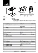
Fig. 27:
Outside dimensions of the
control unit.
Fig. 28:
Installation dimensions of
the control unit.
Fig. 26:
Dimensions of the
supply air unit
Control unit
Size
W+H+T
mm
82+82+30
Assembly size
Ø W
mm
60
Ø D
mm
22
16. Appendix
16.1. List of parameters
The following table lists all of the parameters that are displayed on the control unit, some of which may be changed.
Section 9.3.4. „Parameter settings menu“ gives full instructions on operating and setting the corre
-
sponding parameters.
No.
Consequence
Range of values
Factory setting
P 1
Mini.set-point temp. that can be set on the control unit
10 °C to 20 °C
16 °C
P 2
Max. set-point temp. that can be set on the control unit
20 °C to 35 °C
24 °C
P 3
External release
AUTOMATED
ACKNOWLEDGED
AUTOMATED
P 4
I - component
5 ... 20
10
P 5
P - component
5 ... 20
10
P 6
Temp. correction of the ambient temp. sensor on the control unit -5 °C ... 5 °C
0
P 7
Address
1 - 247
1
P 8
Baud rate
2400 / 4800 / 9600 / 14400 /19200
9600
P 9
Fan calibration supply air
800 - 1200
1.000
P 10
Fan calibration extract air
800 - 1200
1.000
P 13
Type
S / PV / P
S
P 14
Sensor type
CO2 / VOC / EXT.CTRL.
Units / Model
P 15
Minimum ventilation supply air
P 16
Minimum ventilation extract air
P 17
Basic ventilation supply air
P 18
Basic ventilation extract air
P 19
Intermittent ventilation supply air
P 28
Intermittent ventilation extract air
P 20
Air quality
CO2 / VOC
1400 ppm
P 21
Type of regulation
SUP.AIR TEMP.CON / ETA TEMP.CTRL /
ROOMTEMP.CONTROL
SUP.AIR TEMP.
CON
P 22
Selection of heating system
HEATING / COOLING / HEATING-COOLING
/ HEATING-COOLING DIRECT EVAPORATO
HEATING
P 23
Sensor measuring range min.
0 ppm
P 24
Sensor measuring range max.
2000 ppm
P 25
Supply air filter
0 - 500 Pa
100 Pa
P 26
Extract air filter
0 - 500 Pa
100 Pa
P 27
Calibrate filter
P 29
rotor
1000 - 7600
P 30
Extended running time
1 - 60 mins
5 MIN.
W
H
T
Ø
W
Ø
D


