39
b)
4
d)
3
4
c)
1
3
4
a)
3
1
4
2
3
1
A
A (1 : 10)
00
128625
G
A
A (1 : 10)
00
128625
1
2
3
A
21,0° 1 100%
100%
21,0° 1 0%
0%
English
Fig. 18
Welding of the new round
belt.
Fig. 19
Welding the drive belt (3) with clamp (1)
and welding paddle (2).
Fig. 20
Make sure that the belt is running
smoothly on the pulley..
Fig. 15
Remove the lower control board
and the cover.
Fig. 16
Opening for replacing the round belt.
Fig. 17
Removing the defective
drive belt.
Fig. 22
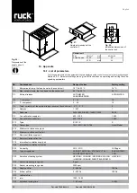
(2) Guide rail for air filter.
Abb. 23
(3) Air filter extract air M5
The differential pressure increases as an air filter becomes more clogged. When the pressure reach
-
es the value set on the corresponding pressure sensor, this can be seen on the status display. The
filter must be changed when the level of clogging reaches 100%. To reset the filter display after
changing the filter, press buttons A (▲ and ▼) at the same time until the clogging level display shows
0% again. The filter change counter will then increase by one.
To ensure that the air filter is changed correctly, proceed as follows:
•
The air filter can be removed without the use of tools.
•
The air filter should be replaced if severely clogged.
•
When changing the filter make sure that the filter frame is sitting correctly on the guide rail in the
device.
•
Finally, the filter display should be reset and the new air filter calibrated (see Section 9.4. “Cali
-
brate filter”)
10.3.3. Air filter
Fig. 21
(1) Air filter supply air F7
Status display:
Reset the display:
Supply air filter
Extract air filter
www.ruck.eu


