


23
EN
Fault
Possible cause
Remedy methods
■
Fan does not start
■
No power supply
■
Impeller does not rotate freely
■
Set-point value differential pressure is set
to 0 Pa.
■
Supply lead not connected.
■
The regulator is not switched on.
■
Check mains supply / connections
■
Find out the causes and, if possible, remove
the fault. If not possible, contact the supplier.
■
Adjust set-point value differential pressure.
■
Have electrical power supply connected by an
authorised electrician.
■
Switch on regulator. - With remote control
(optional) - with a contact between X5 and X6
■
Motor overheated
/ temperature pro-
tection is tiggered
■
Fault of the ball bearings
■
Too high operating temperature
■
Air flow is too low, motor cannot cool down
■
Contact the supplier
■
Observe the data on the nameplate
■
See fault „Low air flow“
■
Device too noisy /
casing vibrations
■
Dirt deposits on the impeller
■
Imbalance of the impeller
■
Connection with intake or exhaust pipe /
duct causes vibrations / oscillations
■
Fixing screws released
■
Fault of the ball bearings
■
Loose impeller blade
■
See chapter maintenance and cleaning
■
Contact the supplier
■
Install fan with vibration dampers
■
Tighten screws
■
Contact the supplier
■
Contact the supplier
■
Low airflow
■
Impeller runs in the wrong direction (wrong
air transport direction)
■
High pressure losses in the system
■
Return flaps closed or only partially open
■
Duct system clogged
■
Speed control incorrectly set / incorrectly
connected
■
Note the marking on the device / nameplate.
Check electrical connections
■
Improve piping configuration or select a more
powerful fan
■
Check drive system / installation position of
the return flap
■
Remove blockage / clean protective grille
■
Check settings / switching unit and possibly
adjust / connect
■
No regulation!
■
Pressure measured in the wrong place
■
Connect the longer pressure measurement
hose to a suitable point in the ventilation
duct
■
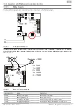
No ModBus com-
munication
■
Jumper J2 is set to control unit
■
Set jumper J2 to ModBus
■
Remote control
unit shows ERR
■
Jumper J2 is set to ModBus
■
Set jumper J2 to control unit
■
Jumper J1 set to
tacho signal Fan
does not run and
green LED D23
flashes quickly
■
Motor has a fault relay
■
Error input not connected
■
Bridge in fault input
■
Motor defective
■
Set jumper J1 to the error relay
■
Set jumper J1 to the error relay and connect a
bridge to the error input
■
Set jumper J1 to the error relay
■
Contact service
■
Jumper J1 set to
tacho signal Fan
does not run and
green LED D23
flashes quickly
■
Motor has a tachometer signal
■
Error input not connected
■
Motor defective
■
Set jumper J1 to tacho signal
■
Connect a bridge to the error input
■
Contact service
F10
FAULT
FAN
F10
FAULT
FAN
www.ruck.eu |


