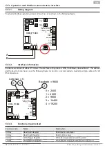
Ruck Ventilatoren DHA EC CP 20 Series Installation, Operating And Maintenance Instruction Download Page 21

21

EN

Servicing, troubleshooting and cleaning may only be performed by specialised personnel in accordance 

with this installation and operating manual and the regulations in force.


Make sure that no connections or components are loosened unless the device is disconnected from 

the mains. Make sure that the equipment cannot be switched back on again.


Individual components must not be interchanged. For example, the components intended for one pro-

duct may not be used for other products.


The regular maintenance and care of our devices is designed to ensure proper function, value retention 

and avoidance of damage. Keep a maintenance log.


Perform the specified maintenance on the unit at the specified intervals.

14.  MAINTENANCE AND CLEANING

Our devices require little maintenance when operated properly.
The following work should be performed at regular intervals, in accordance with health and safety regulations:


Check the operation of the control system and safety devices.


Check electrical connections and wiring for damage.


Remove any dirt from the fan impeller or impellers and from inside the fan housing in order to prevent any unba-

lance or reduction in output.


– Do not use aggressive or easily flammable products for cleaning (impellers/housing). 


– Preferably only water (not flowing water) or mild soapsuds should be used.


– The impeller should be cleaned with a cloth or brush.


– Never use a high-pressure cleaner.


– Balancing clips must not be moved or removed.


– The impeller and fittings must not be damaged in any way.


Pressure fittings and hoses should be checked regularly for impurities and, if necessary, they should be cleaned, 

respectively the pressure hoses should be replaced.

Before putting the unit back into operation after maintenance and servicing work, carry out a visual inspection as 
described in section 11. and 12.

14.1.  Checklist Maintenance and Service

Description

check interval

Triggering device

monthly


Fan

Check fan for function and operational readiness (test run at least 15 minutes)

every 6 months

Check fan for function and operational readiness (test run at least 1 hour)

yearly

Check for dirt, damage, corrosion and fastening

every 6 months

Function-preserving cleaning

every 6 months

Check impeller rotation direction

yearly

Check flexible connections for leaks

yearly

Check impeller for imbalance

yearly

Check protective device for function

yearly


Motor

Check externally for dirt, damage, corrosion and fastening

every 6 months

Function-preserving cleaning

yearly

Check bearing for noise

yearly

Check terminals for tight fit

yearly

Measure the voltage

yearly

www.ruck.eu  |  

Summary of Contents for DHA EC CP 20 Series

Page 1: ...D STORAGE 8 10 ASSEMBLY 9 11 ELECTRICAL CONNECTION 13 12 COMMISSIONING 15 13 OPERATION 15 14 MAINTENANCE AND CLEANING 21 15 LIFETIME AND DISPOSAL 22 16 TROUBLESHOOTING 22 ruck Ventilatoren GmbH Max Pl...

Page 2: ...the product The product has been manufactured according to the accepted rules of current technology There is however still a danger of personal injury or damage to equipment if the following general s...

Page 3: ...re 3 GENERAL SAFETY INSTRUCTIONS Planners plant engineers and operators are responsible for ensuring that the product is installed and operated correc tly Use our devices only in perfect technical con...

Page 4: ...area In this manual there are safety instructions before the steps whenever there is a danger of personal injury or damage to the equipment The measures described to avoid these hazards must be observ...

Page 5: ...Before performing any work on conductive parts al ways disconnect the unit completely from the electri city supply and make sure that it cannot be switched back on again Never reach into the impeller...

Page 6: ...functional and easy accessible Only authorized personnel is allowed to operate the setting mechanisms of the components or parts under the provision that the system is used as intended In an emergency...

Page 7: ...em number SN Serial number Product name Test date CE marking 6 DELIVERY CONTENTS 1 x roof fan with constant pressure control 1 x Installation operating and maintenance instructions EC Declarations of...

Page 8: ...weight see technical data It should be transported with suitable lifting equipment in the original packaging or on the transport equipment indicated If transported with a forklift it should be ensured...

Page 9: ...ssible for maintenance and cleaning purposes The unit should only be installed with authorized and suitable fastening materials at all fastening points Do not distort the unit when installing Just use...

Page 10: ...enance instructions 10 1 Mounting on roof socket DSF 10 2 Mounting of electrical connection Connection power supply Release screws 1 Remove cover 2 Perform the wiring according to the terminal diagram...

Page 11: ...scale drawing Protection Mark according to ISO16016 mm mm General tolerances DIN ISO 2768 mK 1 17 ruck Ventilatoren Max Planck Str 5 D 97944 Boxberg Accesorii DVN_4 Intern 04 129688 ruck Ventilatoren...

Page 12: ...i DVN_8 Intern 04 129688 62 736 kg A4 Do not scale drawing Protection Mark according to ISO16016 mm mm General tolerances DIN ISO 2768 mK 1 22 ruck Ventilatoren Max Planck Str 5 D 97944 Boxberg Acceso...

Page 13: ...rovided in the supply line Use a separate cable inlet for each cable Any cable inlets that are not used must be sealed so that it is airtight All cable inlets must have strain relief Create equipotent...

Page 14: ...eration electric motors heat up Under certain circumstances excessively high ambient or fluid temperatu res heavy contamination etc the motor temperature may exceed the safety limit of the electricall...

Page 15: ...in the duct Setting of the desired differential pressure see 13 Operation 13 OPERATION CAUTION Isolate electrical installation NIGHT DAY Adjust set point After removing the cover you have free access...

Page 16: ...easing and decreasing the set point for NIGHT 3 Control cable 4 Display OFF when regulator on when regulator off PA 150 50 0 13 2 1 Adjustment of the control unit parameter 5 sec M A 2 sec M A B or OF...

Page 17: ...settings menu menu P by pressing the ON OFF button which must be held down for approx 10 seconds Parameter P01 is displayed on the screen With the A and buttons on the control unit the individual P pa...

Page 18: ...rreicht setpoint reached DHA EC CP 20 EC O CP S EN Installation operating and maintenance instructions 13 3 Operation with Modbus communication interface 13 3 1 Wiring diagram 13 3 2 Interface informa...

Page 19: ...Reserved integer R W 40011 10 Set point day Pressure PA integer R W 40012 11 Set point night Pressure PA integer R W 40013 12 day night switching 0 Day time operation 1 Night time operation integer R...

Page 20: ...ressure PA integer R W 30006 5 Reserved integer R W 30007 6 Reserved integer R W 30008 7 Reserved integer R W 30009 8 Reserved integer R W 30010 9 Reserved integer R W 30011 10 Reserved integer R W 30...

Page 21: ...sily flammable products for cleaning impellers housing Preferably only water not flowing water or mild soapsuds should be used The impeller should be cleaned with a cloth or brush Never use a high pre...

Page 22: ...e disposed of professionally and properly after disas sembly in accordance with national and international laws and regulations The same applies to excipients in use such as oils and fats or other sub...

Page 23: ...rong direction wrong air transport direction High pressure losses in the system Return flaps closed or only partially open Duct system clogged Speed control incorrectly set incorrectly connected Note...

Page 24: ...t 17 11 2022 mdar_pb_16d_k10001_en We reserve the right to make changes Language English ruck Ventilatoren GmbH Max Planck Str 5 D 97944 Boxberg Windischbuch Tel 49 7930 9211 300 Fax 49 7930 9211 166...

Reviews: