Peakmeter series 1252
Seite 6-2 Operating instructions
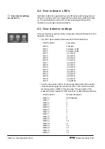
6.2. Over indicator LEDs
Overload conditions are signalled by a red LED above each display channel.
When an overload condition is registered the corresponding OVR-LED lights
up. The overload LEDs will be lit for 0.5 seconds longer than the OVR
condition is true to ease overload indication.
6.3. Over detector settings
There are two rotary switches for the configuration of the OVR detector on the
backside of the meter.
The REF signed switch determines the OVR threshold level.
Switch position
Level value
REF 0
Fullscale
REF 1
Fullscale -1LSB
REF 2
Fullscale -2LSB
REF 3
-0,1 dB FS
REF 4
-0,2 dB FS
REF 5
-0,5 dB FS
REF 6
-1,0 dB FS
REF 7
-2,0 dB FS
REF 8
-3,0 dB FS
REF 9
-4,0 dB FS
REF A
-5,0 dB FS
REF B
-6,0 dB FS
REF C
-7,0 dB FS
REF D
-8,0 dB FS
REF E
-9,0 dB FS
REF F
-10,0 dB FS
You also can set the number of consecutive data words with a specific
value required to trigger an overload condition. This number is set with
the rotary selector SMPL at the rear panel. The word width of the
measured signal, needed for OVR calculation, is detected automatically.
Switch position
Number of samples
SMPL 0
OFF/disabled
SMPL 1
1
SMPL 2
2
SMPL 3
3
SMPL 4
4
SMPL 5
5
SMPL 6
6
SMPL 7
7
SMPL 8
8
SMPL 9
9
SMPL A
10
SMPL B
11
SMPL C
12
SMPL D
13
SMPL E
14
SMPL F
15
Over detector settings
see section 3.3.

