Peakmeter series 1252
Operating instructions Page 6-1
6. Operating instructions
The series 1252 peakmeter work after powering and connecting a digital
audio signal to its input. Absent or invalid signals cause the first two seg-
ments of the bars blinking.
The 1252 can handle three different digital audio standards: AES/EBU
standard, SPDIF standard and OPTICAL-SPDIF standard.
AES/EBU input is transformer balanced, SPDIF input is unbalanced. This
two signals and the one, extracted out of the optical input are selected
automatically and feeded to a digital receiver circuit for further processing.
The selected signal is available at a buffered and transformer balanced
output. This configuration makes it possible to connect the peakmeter in a
signal path.
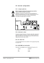
To use the peakmeter as a terminal unit you have to set the internal jumper
to activate the terminating resistor installed in the unit. Failure to do this can
result in display malfunctions when long connection leads are used. The
position of the jumper is marked in the unit.
Autoselection if more than one input signals follows this sequence: AES/
EBU, SPDIF and OPTICAL signal.
The AES/EBU receiver IC outputs the decoded digital signal to the digital
signal processor (DSP), which processes the audio signal and calculates
the display data.
This data is then transfered to a microcontroller, which calculates the
display values and outputs them to the display driver transistors as pulse-
width modulated signals. It also generates the signals for controlling the
display cathodes.
Warning: Power supply failures interrupt the passage of the signal
looped through the unit.
6.1. Measuring characteristics
There are two scale modes/measuring characteristics available: digital
without integration time and quasi-analog with integration time. Selection
is by shifting the scale to the desired mode.
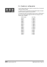
In both modes the headroom range is intensified lighted. The 0 dB
sensitivity of the analog mode is determined by the headroom setting
(described in section 6.4.).
In analog mode also, intensified lighted segments indicate the starting
value of the headroom refer to fullscale.
Please note that the scale slider button must be pushed until it locks
on either one end of the scale. If it does not enter the final position
the required settings for integration time or ballistics may not be set
correctly.
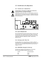
Terminating resistor see
section 6.5.1. und 6.5.4.
Headroom configuration
see section 6.4.

