CHAPTER 10
Tech Tips
Frequency Interaction
Unfortunately, radio frequency (RF) channels cannot be
randomly selected for use in radio devices. They must be
selected to avoid know frequencies in use, FCC restrictions on
the location of devices, and even interference between your own
RF devices. The factory defined frequencies (Groups 01A-24)
selected by RTS for this wireless system are chosen to minimize
possible interference.
Microphone Gain Adjustment
The microphone gain controls on the base station and beltpack
are set to mid-levels by the factory. In most cases this setting
will work fine and only on loud speech will the over-modulation
(OM) indicator light. However, in environments where the
background noise is loud or the user has a strong/quiet voice,
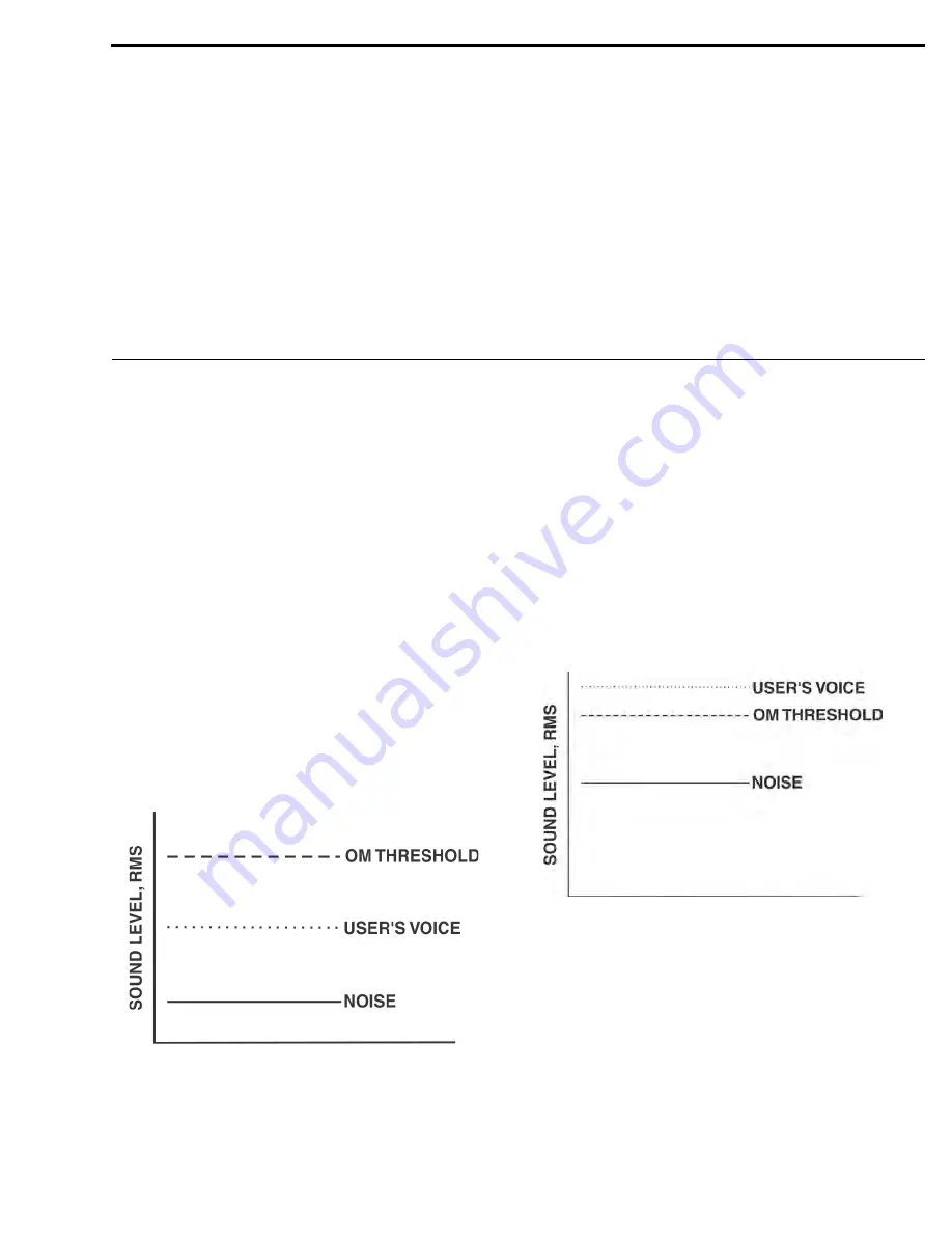
the gain control will need to be adjusted. In Figure 40 the gain is
set correctly. The user’s root-mean-square (RMS) sound level is
well below the OM threshold and only on peaks does his or her
voice flash the OM indicator light.
FIGURE 40.
Low Noise Environment Microphone Gain Set
Correctly
Figure 41 displays the same gain setting as in Figure 40 but
brought into a high noise environment. The user’s voice now
lights the OM indicator all the time he or she speaks due to the
higher noise plus the user speaking louder. The result on the
system is distortion on louder speech. The microphone gain
must be reduced. The same applies to a user with a powerful
voice. If someone sets the system mic gain to their voice and
user has a much stronger voice, then the gain will need to be
reduced, even if the background noise is the same.
Always remember to set the microphone gain based on the
situation and location in which the equipment will be used. If
the equipment is used on the field during a football game, set the
gain based upon a loud stadium, NOT a quiet stadium 2 hours
before a game. If a production studio users has a quiet voice, set
the gain to their voice and NOT the stage hand’s loud voice who
helped set up the system.
FIGURE 41.
High Noise Environment Microphone Gain Set
Too High
Summary of Contents for BTR-800
Page 2: ...2 BTR 800 TR 800 TR 825...
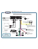
Page 6: ...8 Introduction BTR 800 TR 800 TR 825 FIGURE 1 BTR 800 Block Diagram...
Page 10: ...12 BTR 800 Base Station BTR 800 TR 800 TR 825...
Page 14: ...16 TR 800 Beltpack BTR 800 TR 800 TR 825...
Page 18: ...20 TR 825 Beltpack BTR 800 TR 800 TR 825...
Page 32: ...34 Initial Equipment Setup BTR 800 TR 800 TR 825...
Page 34: ...36 Pre Walk Thru Checklist BTR 800 TR 800 TR 825...
Page 70: ...72 System Operation BTR 800 TR 800 TR 825...
Page 72: ...74 System Walk Thru BTR 800 TR 800 TR 825...
Page 74: ...76 Troubleshooting BTR 800 TR 800 TR 825...
Page 76: ...78 Tech Tips BTR 800 TR 800 TR 825...
Page 78: ...80 Battery Information BTR 800 TR 800 TR 825...
Page 80: ...82 Intercom Systems Specifications BTR 800 TR 800 TR 825...
Page 84: ...86 Accessories and Replacement Parts BTR 800 TR 800 TR 825...