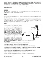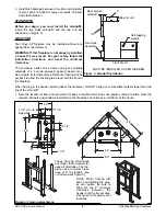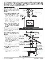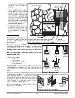
NOTE: If the chase is enclosed or flashed to a roof as shown in (Figure 10), then the flashing must be vented.
If required by local codes, make certain that the walls have been properly insulated, vapor sealed and sheathed
with a fire rated gypsum board (See Figure 11).
REMEMBER:
Check local codes concerning installation requirements and restrictions in your area.
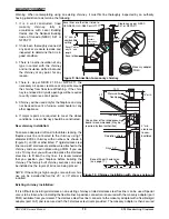
RADIATION SHIELD
A radiation shield must be in place where the chimney passes through each floor level overhead. This will assist
in retarding any spread of fire and act to contain the fire within the area below the fire-stop.
OFFSET CHIMNEY
Maximum offset angle:
45°
Maximum number of elbows:
4, resulting in two (2) offsets.
An elbow may be installed directly on top of the fireplace if required.
Use the offset option if you need to clear a joist or pass around a cupboard.
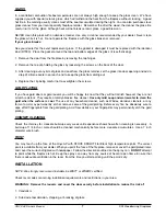
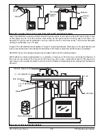
Install the fireplace and chimney as described earlier. When you require an elbow, proceed as follows:
See the detailed offset chart in the EXCEL installation instructions.
1. Install the required elbow. Turn it in the desired direction, and fasten it to the other section with the 3 metal
screws provided at the joint.
2. Install the lengths required to obtain the desired offset. Secure each joint with 3 metal screws.
3. Use another elbow to return the chimney to the vertical direction.
4. Install a roof support, wall support, or an offset support at each offset to support the weight of the flue (elbows
are not designed to support a flue above an offset).
SEALING
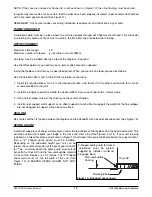
Be sure to seal the 1/4" space between the fireplace and the standoffs with a bead of silicone sealer. (See Figure 15.)
SPARK GUARD
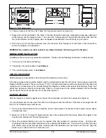
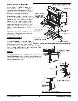
Install a 5" wide piece of sheet metal centered under the joint between the fireplace and the hearth extension. This
will make certain that sparks can't lodge in the crack and start a fire (See Figures 2 & 14). If your unit is being
installed as a raised fireplace as indicated in (Figure 13) and does not require the Micore board (see next section),
then a "Z" shaped spark guard must be installed.
Depending on the allowable height your unit can be
raised, the vertical dimension of the spark guard will dif-
fer. The minimum depth the spark guard must extend
beneath the Onyx AP and the non-combustible material
in front of the fireplace is 2 1/2 inches. The "Z" shaped
sheet metal must run the full width of the unit. (See
Figure 13) (Z-SHAPED SPARK GUARD NOT SUP-
PLIED)
ONYX AP Owner's Manual
RSF Woodburning Fireplaces
15
Z-shaped spark guard for raised
installation must be custom
supplied by installer (minimum
26 gauge steel)
Figure 13: Z-shaped spark guard
Raised platform
Onyx AP
Non-combustible
flooring

