Page 15
ROYAL ENFIELD 350cc and 500cc O.H.V. WORKSHOP MANUAL
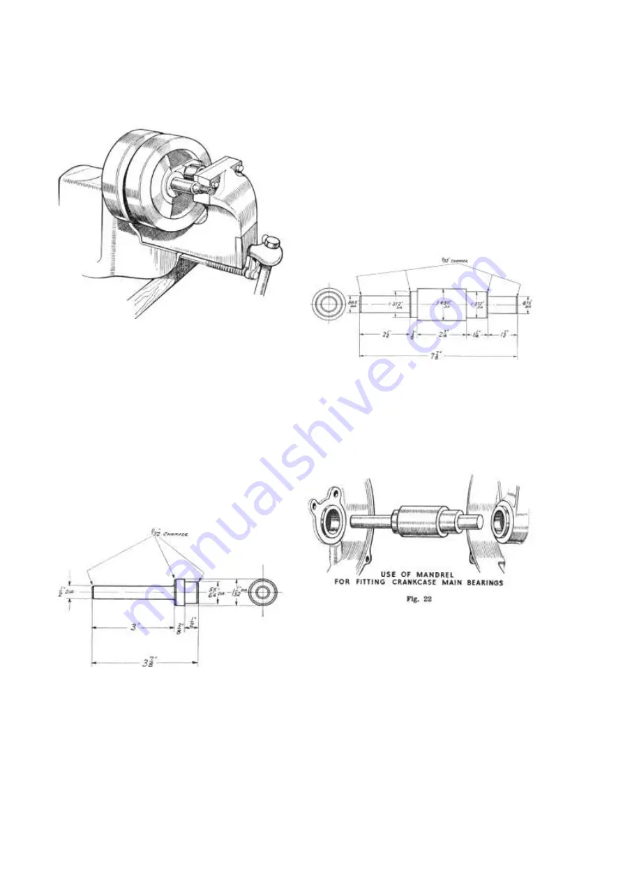
ASSEMBLING FLYWHEELS IN VICE
Fig. 19
the truth of the shafts which is important, the rims and
sides of the wheel do not really matter and may run
out .005 or .010 in. When finally tightened up and
trued, make sure that the big-end bearing has .010 -
.020 in. side play.
20. Removal of Crankcase Main Bearings.
The bearing race can be removed from the timing
side of the case by pressing it out by means of the
bronze oil sealing bush. To do this, support the half
case on a tubular block having an inside diameter of 1
in., then press the oil sealing bush right through, using
a drift as shown in Fig. 20. This will bring out the
DRIFT FOR REMOVING TIMING SIDE BUSH &
ROLLER RACE
Fig. 20
main bearing race and the thrust washer between the
bush and the race. The thrust washer will probably be
damaged in the process so that a new one will be
necessary.
To remove the main bearing race from the driving
side of the case, the half case should be inverted over
a lighted gas ring until the heat loosens the race so
that it falls out on tapping the case.
21. Replacing Crankcase Main Bearings.
In order to ensure that the timing and driving side
main bearing races are in line a mandrel such as is
shown in Fig. 21 should be used. The races are
MANDREL FOR FITTING CRANKCASE MAIN BEARINGS
Fig. 21
inserted about half way into their housings and the
case assembled with the mandrel in position in the
bearings (see Fig. 22). Application of pressure to each
end of the mandrel in turn will then force the races
home and at the same time ensure that the two races
are in line.
22. Reassembly of Crankcase.
Proceed in the opposite order to that employed in
dismantling the case. Make sure that all parts are
perfectly clean before reassembling. Put clean oil on
the shafts and roller bearings. The joint face between
the two halves of the case must be made with gold
size, shellac or a similar jointing compound. Before
fitting the driving side of the case make sure that the
magdyno strap is in position over its studs. When
assembled, check for end float in the mainshaft, which
should be from .005 - .015 in. If necessary the amount
of end float must be adjusted by using main bearing
thrust washers of different thicknesses.
www.hitchcocksmotorcycles.com


