ROYAL ENFIELD 350cc and 500cc O.H.V. WORKSHOP MANUAL
Page 12
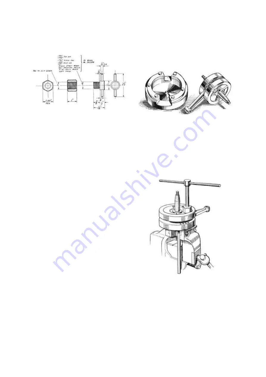
PUMP WORM EXTRACTOR
Fig. 13
behind it, taking care not to damage the bush. Remove
the paper cylinder base joint washer and the magdyno
pinion (see Para. 11), loosen the strap securing the
magdyno and remove this; also the timing pinion key
and engine sprocket key. Next unscrew the two 5/16
in. nuts just below the magdyno (one each side of the
case), the 5/16 in. nut below the front of the cylinder
on the left side and the nuts from one end of the two
5/16 in. studs passing through the case near the
bottom. Then remove the nuts from one end of the
seven 1/4 in. studs which hold the two halves of the
crankcase together. Before parting the two halves of
the case, as much oil as possible should be drained out
by removal of the two oil filter plugs. Even so, a small
amount of oil will probably be left in the case. To
prevent this running over the work bench, rest the case
on the timing side in a clean tray and lift off the
driving side. The joint will require breaking by a sharp
tap with a soft mallet, after which the driving side can
be lifted off quite easily. Lift the driving side rollers,
cages and thrust washer off the shaft and the flywheel
assembly out of the timing side of the case.
15. Removal of Tappets and Guides.
If the tappet stems, feet or guides are badly worn
they must be renewed. The guides are a press fit in
the crankcase and can be removed by knocking them
upwards with a hammer and drift. The first part of
this operation can be done by placing the drift against
the tappet foot but for the last part a slightly bent and
flattened drift must be used against the lower end of
the guide itself. After removal of the guides the inlet
tappet can be lifted out but to remove the exhaust
tappet it is necessary to knock out the cam spindle.
The only satisfactory way of doing this is by dividing
the crankcase and knocking out the spindle from
inside.
16.
Dismantling Flywheels.
If the big-end bearing requires renewal the
flywheels must be separated. To do this use the
flywheel assembling jig (Fig. 14) if available,
otherwise grip one of the mainshafts in a vice fitted
with lead jaws and prevent the wheels from turning
by inserting a stout rod between the vice and the edge
of the balance weight on the lower wheel (see fig 15).
From the upper wheel remove the set screw which
prevents the crankpin nut from turning and unscrew
this nut, using a well-fitting tubular spanner for this
purpose. The crankpin is a press fit in the flywheel
FLYWHEEL ASSEMBLY JIG
Fig. 14
and to drive it out the upper wheel must be supported.
For this purpose two pieces of channel iron may be
used (see Fig. 16). The pin can then either be pressed
out or knocked out using a heavy hammer and a stout
brass or aluminium drift. Lift the connecting rod
floating bush and thrust washers off the crankpin. If
the crankpin requires renewal, grip the remaining
flywheel in a vice, remove the other crankpin nut and
drive the pin out of the wheel.
DISMANTLING FLYWHEELS IN VICE
Fig. 15
17.
Connecting Rod.
Wear in the hardened steel big-end bush will be
shown by the formation of a ridge round the centre of
the bearing surface corresponding with the oil groove
in the white metal bush. If this wear is excessive the
rod should be replaced and returned to the Works for
www.hitchcocksmotorcycles.com


