background image

Grand

STAR

 Internet Jukebox 

Parts Catalog 

22022603  

8-33 


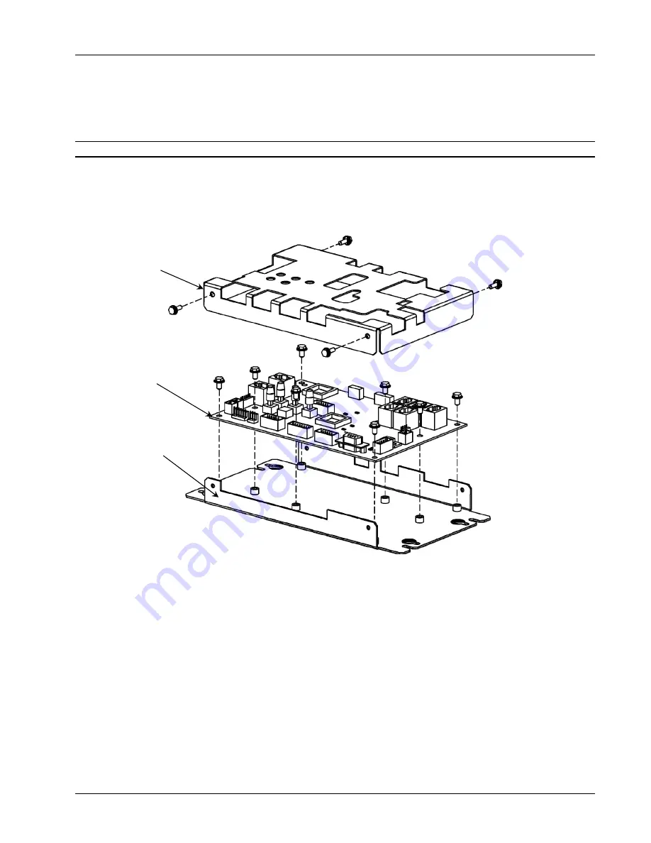
Rowelink Controller Assembly 

Refer to 

Figure 8-1.9


Ref. Part 

No. Description 

Qty 

  40955703 Rowelink 

Controller 

Assembly 

.................................................................... 

Ref 

  1 

40925908 

Cover - Rowelink Controller ............................................................................ 1 

  2 

61135706 

Circuit Board Assembly - Rowelink Controller ................................................ 1 

  3 

40925802 

Base - Rowelink Controller ............................................................................. 1 


Figure 8-19 –


Rowelink Controller Assembly 


Summary of Contents for GrandSTAR

Page 1: ...GrandSTAR Internet Jukebox 22022603 Volume 1 of 1 Rev G...

Page 2: ......

Page 3: ...provided for your safety If the provided plug does not fit into your outlet consult an electrician for replacement of the obsolete outlet 10 Protect the power cord from being walked on or pinched par...

Page 4: ...ic shock to persons CAUTION The exclamation point within an equilateral triangle is intended to alert the user to the presence of important operating and maintenance or servicing instructions WARNING...

Page 5: ...or 1 4 System Power Supply 1 4 Transformer Assembly 1 4 Rowelink Controller 1 4 LED Controller 1 4 Router 1 4 Dial Up Modem 1 4 Volume Control Unit 1 5 4 Channel Preamplifier 1 5 1000 Watt Audio Digit...

Page 6: ...er taps 3 5 Combine Power Consumption of all Speakers 3 6 Amplifier Overload Check 3 7 Speaker Synopsis 3 11 1000 Watts of RMS Power per Amplifier or 500 Watts per Channel 3 11 SECTION 4 ADDING MICROP...

Page 7: ...ier 7 3 Yellow Clip LED 7 3 Red Overload LED 7 3 Computer Core Assembly 7 3 Hard Drive Green LED 7 3 Hard Drive Red LED 7 3 Sequence of Operation 7 4 Troubleshooting Charts 7 12 SECTION 8 PARTS CATALO...

Page 8: ...iew with Lower Door Removed 8 22 Bill Acceptor Assembly 8 24 Core Computer Assembly Exploded View 8 26 LED Controller Assembly 8 28 Transformer Assembly 8 29 Power Supply Assembly 8 30 4 Channel Pream...

Page 9: ...st of Tables Table 3 1 Extension Speaker Worksheet Sheet 1 3 3 Table 3 2 Extension Speaker Worksheet Sheet 2 3 4 Table 3 3 Extension Speaker Worksheet Sheet 3 3 5 Table 3 4 Extension Speaker Worksheet...

Page 10: ...Tables GrandSTAR Internet Jukebox viii 22022603 This page intentionally left blank...

Page 11: ...phone Connections 4 1 Figure 4 2 Paging Microphone Setup Screen 4 2 Figure 4 3 VCU Setup Screen 4 3 Figure 5 1 IR Remote 5 1 Figure 5 2 LED Control Assembly 5 4 Figure 5 3 Program DIP Switches 5 4 Fig...

Page 12: ...ure 8 13 Core Computer Assembly Exploded View 8 26 Figure 8 14 LED Controller Assembly 8 28 Figure 8 15 Power Transformer Assembly 8 29 Figure 8 16 Power Supply Assembly 8 30 Figure 8 17 4 Channel Pre...

Page 13: ...his network is a digital platform that delivers music across the Internet to Rowe Jukeboxes anywhere The GrandSTAR jukebox is an Internet enabled jukebox that allows all the traditional functions of a...

Page 14: ...apacity Unwanted music categories can be blocked Quarter Coin Acceptance Bill acceptance of 1 5 10 and 20 1000 bill capacity Web based management Attract mode Music On Demand song download Dynamic sea...

Page 15: ...has examined them Damage claims are your responsibility Do not return damaged merchandise until after your claim has been established Once your claim has been established merchandise may be returned...

Page 16: ...has an IEC 320 power inlet two 6A circuit breakers a 3A breaker unused in GrandSTAR and two 4A fuses Transformer Assembly The transformer assembly supplies power for the Audio Video Controller 1000 W...

Page 17: ...n 3 of the included Network Setup Jukebox Operation Operator Setup Screens manual for other possible configurations 4 Channel Preamplifier This Rowelink module transforms audio signals from the Core C...

Page 18: ...FF SWITCH COIN ACCEPTOR COIN INLET BILL ACCEPTOR LED CONTROLLER SYSTEM POWER SUPPLY AUDIO OUTPUT TRANSFORMER CABINET FAN VOLUME CONTROL UNIT 4 CHANNEL PREAMPLIFIER 1000 WATT DIGITAL AMPLIFIER DIAL UP...

Page 19: ...bit Stereo Frequency Response 20 to 20 000 Hz Channel Separation 90 dB 1 000 Hz Output 0 7 V approx depending on the album Power Amplifier Second 1000 watt Stereo Amplifier is Optional 1000 Watt Ster...

Page 20: ...Unpacking System Description GrandSTAR Internet Jukebox 1 8 22022603 This page intentionally left blank...

Page 21: ...NG Never install or remove a hard drive when the unit is powered ON As an extra precaution always unplug the CC Core Computer from the power source before removing or inserting a hard drive The follow...

Page 22: ...4 Place the hard drive in the housing Note the hard drive connector s relationship to the hooks and secure it by tightening the four spring loaded screws as shown in Figure 2 2 Figure 2 2 Hard Drive I...

Page 23: ...2 3 5 Carefully extend the IDE cable from inside the Core Computer and connect it to the hard drive Locate a 4 pin power connector from the ATX Power Supply and connect it to the hard drive also Refe...

Page 24: ...the access hole in the back panel of the cabinet and plug the other end of the power cord into the Power input of the surge suppressor located on the inside right cabinet back panel 10 Plug the AC co...

Page 25: ...IN POWER IN 12 VDC 24 VDC 24 VAC 5 VDC RS232 P22 CC RL RX CC RL TX P21 COIN ACCEPTOR P20 COIN SWITCHES P19 BILL ACCEPTOR POWER CALIBRATE SERVICE REJECT ROWELINK CONTROLLER 409260XX P3 AMP MUTE P11 IR...

Page 26: ...the jukebox Audio Test Play a local music selection by following the procedure below 1 Browse through album covers on the local jukebox by touching the red arrow keys on either side of the panel showi...

Page 27: ...e which accesses all songs in the AMI Entertainment music library will not work unless the jukebox is connected to the Internet See the included manual Network Setup Jukebox Operation Operator Setup S...

Page 28: ...he jukebox is shipped to you with the Wireless Router Antenna in the horizontal position In some interference prone locations the Antenna is more effective in the vertical position The hole in the top...

Page 29: ...t 2 Loosen the four Router Mounting Bracket Screws and slide the Bracket off the Screws 3 Rotate the Antenna to the vertical position and insert it through the hole in the Cabinet See Figure 2 8 4 Sli...

Page 30: ...Installing Hard Drive Testing GrandSTAR Internet Jukebox 2 10 22022603 This page intentionally left blank...

Page 31: ...watts For example each channel could drive 375 watts directly from the amplifier E1 to E7 and the remaining 125 watts through the transformer taps E1 through E6 and 70V terminals A1 A2 See Figure 3 1...

Page 32: ...s less than 100 feet 4 OHM SPEAKERS PARALLEL CONNECTIONS No more than one 4 ohm speaker should be connected to a speaker line If several 4 ohm speakers are to be used each speaker should have its own...

Page 33: ...rs is set at each speaker Use the Tables 3 1 through 3 4 Worksheets to help you calculate the amount of power consumed by the extension speakers An extension speaker RMS power rating should be at leas...

Page 34: ...__ at 49 watts each ____watts Speakers for the 64 watt taps E1 to E5 ____ at 64 watts each ____watts Speakers for the 100 watt taps E3 to E6 ____ at 100 watts each ____watts Speakers for the 121 watt...

Page 35: ...to E5 ____at 32 watts each ____watts Speakers for the 50 watt taps E3 to E6 ____at 50 watts each ____watts Speakers for the 72 watt taps E1 to E6 ____at 72 watts each ____watts Speakers for the 95 wa...

Page 36: ...less jukebox power to suit your jukebox volume Phono Power Phono Speaker Connections 25 Violet connects to Channel 1 E2 Pink connects to Channel 2 E2 1 Violet connects to Channel 1 E3 Pink connects to...

Page 37: ...acceptable 3 If a yellow CLIP LED is always lit or flickers continuously the amplifier is overloaded and will shut down and you must perform Step 4 If a red OVERLOAD LED on the amplifier flickers the...

Page 38: ...Sound System Setup GrandSTAR Internet Jukebox 3 8 22022603 Figure 3 1 Speaker Connections...

Page 39: ...GrandSTAR Internet Jukebox Sound System Setup 22022603 3 9...

Page 40: ...Sound System Setup GrandSTAR Internet Jukebox 3 10 22022603 Figure 3 2 Audio Output Transformer Wiring Diagram 40832115...

Page 41: ...els wired in series will not give equal outputs and the frequency response may be different To minimize cost it is recommended to utilize Diagram 4 This shows 28 speakers their rating only has to be 8...

Page 42: ...Sound System Setup GrandSTAR Internet Jukebox 3 12 22022603 Figure 3 3 Diagrams 1 5 External Speaker Connections with Jukebox Speakers Connected...

Page 43: ...GrandSTAR Internet Jukebox Sound System Setup 22022603 3 13 Figure 3 3 Diagram 2 Ten Speakers with Jukebox Speakers Connected...

Page 44: ...Sound System Setup GrandSTAR Internet Jukebox 3 14 22022603 Figure 3 3 Diagram 3 Sixteen Speakers with Jukebox Speakers Connected...

Page 45: ...GrandSTAR Internet Jukebox Sound System Setup 22022603 3 15 Figure 3 3 Diagram 4 Twenty Eight Speakers with Jukebox Speakers Connected...

Page 46: ...Sound System Setup GrandSTAR Internet Jukebox 3 16 22022603 Figure 3 3 Diagram 5 Low Voltage and 70 Volt Speakers with Jukebox Speakers Connected...

Page 47: ...GrandSTAR Internet Jukebox Sound System Setup 22022603 3 17 Figure 3 4 Diagrams 1N 3N External Speaker Connections with Jukebox Speakers NOT Connected...

Page 48: ...Sound System Setup GrandSTAR Internet Jukebox 3 18 22022603 Figure 3 4 Diagram 2N 8 Speakers with Jukebox Speakers NOT Connected...

Page 49: ...GrandSTAR Internet Jukebox Sound System Setup 22022603 3 19 Figure 3 4 Diagram 3N 16 Speakers with Jukebox Speakers NOT Connected...

Page 50: ...Sound System Setup GrandSTAR Internet Jukebox 3 20 22022603 Figure 3 5 Volume Control Unit...

Page 51: ...GrandSTAR Internet Jukebox Sound System Setup 22022603 3 21 Figure 3 6 Volume Connections Using Existing 3 Wire or 4 Wire Cable...

Page 52: ...Sound System Setup GrandSTAR Internet Jukebox 3 22 22022603 This page intentionally left blank...

Page 53: ...Adapter and the 4 Channel Preamplifier and installation and operating instructions The 30995201 Paging System with Hand Held Wireless Microphone allows wireless paging and its receiver plugs into the...

Page 54: ...C SETUP to view the Paging Mic Setup screen see Figure 4 2 Make sure all MIC s in the Type column are set to PAGING indicated by BLUE buttons Figure 4 2 Paging Microphone Setup Screen The Microphone V...

Page 55: ...to enter the Main Menu then Touch HARDWARE SETUP Touch VCU Setup to view the VCU Setup screen see Figure 4 3 Figure 4 3 VCU Setup Screen In rows VCU1 VCU4 remove check marks in the columns correspondi...

Page 56: ...Adding Microphones GrandSTAR Internet Jukebox 4 4 22022603 This page intentionally left blank...

Page 57: ...ter 1 each of Red White Green and Blue Black Door 3 White LEDs illuminate the Service Left and Right Accent Lighting Features of the LED Control Assembly 40931103 Figure 5 2 The features of the LED co...

Page 58: ...sic Pot and the Speed Pot the last two are on the LED Control Assy 40931103 The faster the Speed Pot is set the less influence music will have on the LED lighting It is recommended to have a relativel...

Page 59: ...2 Sw 8 ON Sw 7 OFF Pattern 3 Both Sw 7 and Sw 8 OFF Pattern 3 Pattern 1 divides the LED lighting into four groups of 4 LED s this pattern is a sequence of LED switching whereby three LEDs are ON and...

Page 60: ...ptor GrandSTAR Internet Jukebox 5 4 22022603 Adjusting Pattern with the lR Remote Push PATTERN then push either LIGHTS or LIGHTS Cycles through Patterns 1 2 and 3 Figure 5 2 LED Control Assembly Figur...

Page 61: ...ip Switch Settings are Switch Setting Remarks 1 2 ON Fast Pulses 3 OFF 1 Pulse per Dollar 4 ON Always Enabled 5 OFF Pulse Mode 6 7 8 OFF For future use by Coinco In addition the Vantage has several ot...

Page 62: ...the 5 LEDs and their meanings Figure 5 7 Configuration Settings The ON and OFF settings shown are the Rowe default settings 5 Press the Service Mode Button and release to step through the Bill Accept...

Page 63: ...our settings have been saved 8 Refer to the Coinco Installation and Operation Guide included with your jukebox for a more detailed explanation of the various options MEI AE2611 Setup The factory DIP s...

Page 64: ...LED Lighting and Bill Acceptor GrandSTAR Internet Jukebox 5 8 22022603 This page intentionally left blank...

Page 65: ...call This section discusses how to do preventive maintenance procedures Changing music collecting statistic figures and changing other location specific features can be done using the AMI Entertainmen...

Page 66: ...te the touch screen 1 Power on the GrandSTAR jukebox and allow it to complete the startup sequence 2 Open the door of the jukebox 3 Locate the Calibrate button on the Rowelink Controller Refer to Figu...

Page 67: ...s at the site so it is best to check the filter condition at least once a month The filter is located on the back of the GrandSTAR as shown In Figure 6 3 Remove and clean the filter as necessary To do...

Page 68: ...Routine Service GrandSTAR Internet Jukebox 6 4 22022603 This page intentionally left blank...

Page 69: ...or pushed through the back of connectors when mated 2 A defective module Troubleshooting procedures are directed at module replacement not repair A summary of the functions for each of the jukebox s r...

Page 70: ...back to Core Computer Rate is approximately ten times per second Core Computer RL RX LED Should be flashing Indicates when ROWELINK CONTROLLER receives a RL signal from one of the ROWELINK devices App...

Page 71: ...sends a RL signal back to the Rowelink Controller Power Amplifier Yellow Clip LED Should be off If on the input signal to the Power Amplifier is to high which will cause the output signal distortion...

Page 72: ...ney Acceptor sends pulse s to the Rowelink Controller no escrow Rowelink Controller sends money information to the computer via Rowelink Computer increases the credits accordingly Credit is changed on...

Page 73: ...R P14 SHEET 2 Y B O BR W S BR W R Y BL R G Y R Y Y B R Y O B BR W G Y R Y BR W B B B W B B R B W S S Y W B W B CBA SYSTEM PWR SUPPLY 40923409 POWER SUPPLY ASSEMBLY 22145809 N L TO BOTTOM LEAD OF PRIMA...

Page 74: ...NK A RXDb ROWELINK A 34038701 COIN SW 4 ACCEPTOR 9 V COMMON 34032903 CTSb TO CORE COMPUTER COM2 SHEET 4 TO 34039924 HARNESS SHEET 1 BR 34052602 12 V COMMON TO 4 CHPREAMPLIFIER SHEET 3 ROWELINK B P22 D...

Page 75: ...A 9 VDC ROWELINK B 22215003 MUTE NOT 9V COM V P B W B 34054303 TO 40942204 HARNESS SHEET 3A CH2 OUTPUT TO 34032615 HARNESS SHEET 1 30934217 30934217 70 V B W R Y Extremely Cool R Y B B W CH4 34059105...

Page 76: ...O W W G 40942204 BASS SPEAKE R HARNES S W O W R Crossover W O W BL B 2 W R O B O B 34054604 TOP DOOR SPEAKER HARNES S BR G 2 W G 40830806 HORN S O W S W G 2 40830901 MID B 1 W BL 61052707 TO 34054303...

Page 77: ...IN or DDC data I O MONITOR ID 2 IN or reserved MONITOR ID 0 IN GND SIGNAL GND GREEN BLUE GREEN RETURN H SYNC DCDa MONITOR ID 3 IN or DDC clock I O V SYNC RTSa RED RETURN RXDa SYNC RETURN DTRa CTSa BL...

Page 78: ...ed 2 w led 4 w led 1 b com 1 2 com 3 4 120 VAC com 3 4 W led 4 r led 2 w led 1 w 22212814 led 4 r com 1 2 led 1 w com 3 4 com w b W led 3 w led 2 w com 1 2 NC MIDDLE LIGHTING MUTE led 2 w 34045104 AND...

Page 79: ...LS 31 RED 4 70035346 BLUE 4 70035344 GREEN 4 70035345 WHITE 19 70035340 R W 34045102 AND 34045103 BLACK DOOR 34045106 AND 34045107 RED DOOR Y com w b discrete leds B R RED DOOR LED TOTALS 31 RED 8 700...

Page 80: ...Trouble Symptom Probable Cause Application does not boot up At the first boot up screen Detecting IDE Primary Master reports None 1 There is no hard drive in the housing 2 The plugs are not completely...

Page 81: ...omputer ATX power reset button was not pressed in 2 The monitor or its power supply is defective or unplugged The monitor does not work The computer fan is on and all the system s LEDs are normal 1 Th...

Page 82: ...box No sound from jukebox although the application reports Now Playing 1 The volume control is turned all the way down 2 The volume control is broken 3 The 4 Channel Preamplifier is continually muting...

Page 83: ...or the DC adapter plug is not fully inserted in the receptacle on the back of the router The Link Act LED in front of the router does not light up when an Ethernet cable is plugged in the respective p...

Page 84: ...puter 2 The Ethernet cable is not fully seated in the port on the Core Computer or in the back of the router 3 The connection is loose between the modem and the router 4 The cable is bad 5 The Interne...

Page 85: ...mbly Internal View 8 15 Figure 8 8 Component Identification and Location Internal View Left Hand Side 8 17 Figure 8 9 Pilaster Assembly 8 19 Figure 8 10 Component Identification and Location Internal...

Page 86: ...Parts Catalog GrandSTAR Internet Jukebox 8 2 22022603 This page intentionally left blank...

Page 87: ...umber This column lists the part number to use when ordering replacement parts or making inquiries Description This column gives a word description of each part or assembly Each item is indented to sh...

Page 88: ...Parts Catalog GrandSTAR Internet Jukebox 8 4 22022603 Figure 8 1 Front View 3 2 1...

Page 89: ...Black See Figure 8 3 Figure 8 4 Figure 8 5 Ref 61183402 Door Assembly Top Red See Figure 8 3 Figure 8 4 Figure 8 5 Ref 2 61184501 Lower Door Assembly Gold See Figure 8 6 Figure 8 7 Used on Red GrandS...

Page 90: ...Parts Catalog GrandSTAR Internet Jukebox 8 6 22022603 Figure 8 2 Rear View 1 2 3 4...

Page 91: ...2 Ref Part No Description Qty 61184401 Jukebox Assembly Black GrandSTAR Ref 61184402 Jukebox Assembly Red GrandSTAR Ref 1 34089801 Bracket Light Block 3 2 40942702 Frame Filter 1 34053001 Pad Filter N...

Page 92: ...Parts Catalog GrandSTAR Internet Jukebox 8 8 22022603 Figure 8 3 Top Door Assembly External View 4 1 2 3 7 5 8 9 6...

Page 93: ...ker Tweeter 3 2 3 40968201 Panel Outside 1 40969001 Graphics 1 40968202 Panel Inside 1 4 22207201 Panel Graphics Left 1 5 22207101 Panel Graphics Right 1 6 61183501 Top Door Black Silver 1 61183502 To...

Page 94: ...Parts Catalog GrandSTAR Internet Jukebox 8 10 22022603 Figure 8 4 Top Door Assembly Internal View 11 21 7 19 23 3 22 9 8 18 5 10 13 15 15 16 1 4 12 2 1 17 12 6 1 14 20 14...

Page 95: ...2 70093401 Cable Clamp 17 32 2 13 20554502 Clip Cable 4 14 34045105 CBA Backlight LED BD B 3 15 34045104 CBA Backlight LED BD A 3 16 40968001 Bracket Light Lower Mid 2 17 40968101 Bracket Graphics Pan...

Page 96: ...Parts Catalog GrandSTAR Internet Jukebox 8 12 22022603 Figure 8 5 Top Door Assembly Internal Top and Side View 3 1 2 4 5 6 7 8 9 10 11 2 3 7...

Page 97: ...Black GrandSTAR 2 34045106 Circuit Board Assembly Crown Pilaster LED Y R Red GrandSTAR 2 3 34045103 Circuit Board Assembly Crown Pilaster LED R G Black GrandSTAR 2 34045107 Circuit Board Assembly Crow...

Page 98: ...oor Assembly External View Refer to Figure 8 6 Ref Part No Description Qty 61184501 Lower Door Assembly Gold Red GS 1 Ref 61184502 Lower Door Assembly Silver Black GS 1 Ref 1 61184701 Bracket Security...

Page 99: ...ernal View Lower Door Assembly Internal View Refer to Figure 8 7 Ref Part No Description Qty 61184501 Lower Door Assembly Gold Red GS 1 Ref 61184502 Lower Door Assembly Silver Black GS 1 Ref 1 6118480...

Page 100: ...s Catalog GrandSTAR Internet Jukebox 8 16 22022603 Figure 8 8 Component Identification and Location Internal View Left Hand Side 1 23 24 25 26 20 6 8 7 7A 2 3 4 5 11 9 14 10 12 13 15 16 17 18 19 22 21...

Page 101: ...rity 2 11 22162901 Catch Top Door Latch 2 12 40935601 Bracket Security RH 1 13 61143302 Pilaster Assembly RH R G W BL Black GS 1 See Figure 8 9 1 61143303 Pilaster Assembly RH Y R Y R Red GS 1 See Fig...

Page 102: ...Parts Catalog GrandSTAR Internet Jukebox 8 18 22022603 Figure 8 9 Pilaster Assembly Left Hand Shown 1 6 8 2 3 4 5 9 10 11 7...

Page 103: ...103 Circuit Board Assembly Crown Pilaster LED R G Black GrandSTAR 1 34045102 Circuit Board Assembly Crown Pilaster LED BL W Black GrandSTAR 1 34045106 Circuit Board Assembly Crown Pilaster LED Y R Red...

Page 104: ...Parts Catalog GrandSTAR Internet Jukebox 8 20 22022603 Figure 8 10 Component Identification and Location Internal View Right Hand Side 2 3 4 10 6 5 1 8 7 11 12 13 14 15 9...

Page 105: ...omputer and Bracket Assembly See Figure 8 13 1 7 61145101 Lower Coin Chute 1 8 34008301 Chute Slug 1 21792901 Door Slug Cup Not Shown 1 21793001 Bracket Slug Cup Not Shown 1 9 30984404 Holder Assembly...

Page 106: ...Parts Catalog GrandSTAR Internet Jukebox 8 22 22022603 Figure 8 11 Shell Assembly Front View with Lower Door Removed 13 14 15 1 3 5 7 6 8 10 11 9 2 4 12...

Page 107: ...22164602 Circuit Board Assembly White LED 1 7 40954801 Bracket LED Mounting 1 8 40966201 Bracket Router Mounting 1 9 409170xx Bill Acceptor See Figure 8 12 1 10 34045701 Bracket Pilaster Mount 4 11 34...

Page 108: ...l Stacker 1 40917010 Transport and Bracket Assembly Ref 22135609 MEI Bill Acceptor with 1000 Bill Stacker 1 1 40915501 B A Adapter Bezel Bracket 1 21730001 Fall stop Hook 1 22129201 Pivot Bracket 1 2...

Page 109: ...GrandSTAR Internet Jukebox Parts Catalog 22022603 8 25 This page intentionally left blank...

Page 110: ...Parts Catalog GrandSTAR Internet Jukebox 8 26 22022603 Figure 8 13 Core Computer Assembly Exploded View 2 1 10 6 3 4 5 7 8 9 12 11 13 14 16 15...

Page 111: ...Supply Flex ATX SFF 1 7 61188401 Cover Computer Core 1 8 22120602 Modem Internal PCI Low Profile 1 9 40924207 40924208 Single Board Computer 1 26731501 Heatsink CPU Fan Replacement Kit See Note 1 1 1...

Page 112: ...1103 LED Controller Assembly Ref 1 40930903 Cover LED Control 1 2 61142202 Circuit Board Assembly LED Controller 1 3 40922507 Power Supply Universal 1 4 40931002 Base LED Control 1 5 34039107 Fan Chas...

Page 113: ...nsformer Assembly Refer to Figure 8 15 Ref Part No Description Qty 40917103 Transformer Assembly Ref 1 22137601 Transformer Assembly Handle 1 2 34034503 Transformer Mounting Plate 1 3 40737831 Power T...

Page 114: ...2 22118703 Power Inlet IEC 320 C 14 1 3 22145908 Chassis Power Supply 1 4 22141301 Standoff 8 32 x 1 5 4 5 40923409 Circuit Board Assembly Power Supply with Router Reset 1 6 22146002 Cover Power Suppl...

Page 115: ...l Preamplifier Refer to Figure 8 17 Ref Part No Description Qty 40982601 4 Channel Preamplifier Ref 1 40982701 Cover Preamp 1 2 61195201 Circuit Board Assembly 4 Channel Preamplifier 1 3 80713008 8 32...

Page 116: ...sembly Ref 1 61133101 Chassis Audio Output 1 2 30426707 Binding Post Strip 2 3 30426706 Binding Post Strip 1 4 70233206 Bushing Snap Split 1 5 40949203 Circuit Board Assembly Output Resistor 1 6 40633...

Page 117: ...embly Refer to Figure 8 1 9 Ref Part No Description Qty 40955703 Rowelink Controller Assembly Ref 1 40925908 Cover Rowelink Controller 1 2 61135706 Circuit Board Assembly Rowelink Controller 1 3 40925...

Page 118: ...06 19 Flatscreen 1 2 40963701 Monitor Mounting Rear Bracket 1 3 34076002 Monitor Mounting Bracket 2 4 70220351 Foamed Tape 2 5 70220352 Foamed Tape 2 6 61139302 Adaptor Bezel 1 7 61166302 Touch Monito...

Page 119: ...lows customers to use Visa and Master Card 26694913 Second Amplifier Kit Add a second 1000 watt amplifier Includes a power transformer and an output transformer 34037908 100 foot cable for Volume Cont...

Page 120: ......

Reviews:

Related manuals for GrandSTAR