Page 8 of 12
SPI
www.rotork.com
PUB132-002-00_0219
equipment as required), ensuring the keyway is correctly aligned with the valve shaft. The SPI baseplate
should sit square on the valve mounting flange and should not place any sideways forces on the output
shaft. If the SPI unit is a tight fit on the valve shaft, it may be necessary to strike the top of the SPI input shaft
with a soft faced mallet. Excessive force should not be used and if there is any possibility of damaging the SPI
unit, it should be removed, the valve shaft and SPI output shaft bore inspected and any tight spots dressed
out where appropriate.
For thrust taking applications, the threaded valve stem must be thoroughly lubricated with a suitable grease
before fitting the SPI. The SPI should then be offered up to the valve stem, and the input shaft rotated to
thread the output sleeve of the SPI onto the valve stem. The SPI baseplate should sit square on the valve
mounting flange and should not place any sideways forces on the output sleeve. If the output sleeve is a
tight fit on the valve stem, the SPI unit should be removed, the valve stem and output sleeve machining
inspected and any tight spots dressed out where appropriate.
For other valve shaft / stem arrangements, please contact Rotork for further advice on installation of the SPI
unit.
⚠
WARNING
–
Do not strike the SPI unit to aid installation for a thrust taking application, as the thrust
bearings may become damaged and will require replacing.
The SPI is supplied with studs and nuts for mounting to the valve or gearbox. If it is desired to replace these
we recommend grade 8.8 fasteners (640MPa yield strength). The mounting nuts or screws should be
torque-tightened to a maximum of 45Nm (33.1 lb ft.) for non-thrust taking applications or 60Nm (44.3 lb ft.)
for thrust taking applications.
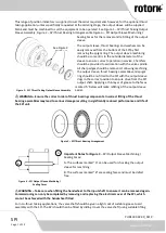
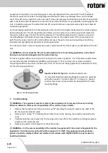
Important Note for Figure 4
It is recommended that adjoining flanges be sealed on assembly
with silicon sealant. The face marked
“
C
”
on Figure 4
Location Face shows where sealant can be applied to the valve
mounting flange.
7
Commissioning
⚠
WARNING
–
The equipment must be isolated / de-energised prior to removal of covers / servicing.
Failure to adhere to this may lead to possibility of fire, serious injury or death.
1.
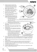
Remove the handwheel and the 4 small screws
“
D
”
attaching the indicator plate to the shaft of the
SPI. Remove the indicator plate.
2.
Remove the 4 screws
“
E
”
attaching the electrical cover to the housing, these will be retained by the
cover.
3.
Carefully prise the cover away from the housing and remove from the assembly, retaining any grease
present on the central lip seal.
4.
Remove any plastic transit plugs from the cable entries.
⚠
WARNING
–
It is the sole responsibility of the installer to supply and fit the correct cable glands for the
application. The cable entries on the SPI unit are tapped ½”–
14 NPT. Only appropriate entry reducers,
glands or conduit, suitably certified and selected in accordance with EN/IEC 60079-14, may be used in
hazardous locations.
C
w
Figure 4
–
Sealant Location Face

