Page 10 of 12
SPI
www.rotork.com
PUB132-002-00_0219
12.
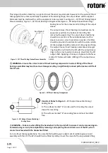
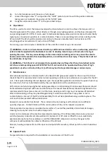
Rotate the cam disc to one of the other
available orientations to allow the cams to
be positioned as desired, then replace the
cam disc over the screw heads
“
I
”
and re-
tighten to the prescribed torque.
13.
Refit the plastic setting ring “H” over the
main SPI shaft “G”, ensure to rotate
the ring
so it seats fully down on the cam disc.
14.
Loosen the 2 nuts
“
J
”
holding the closed
(short) cam onto the cam disc.
15.
Slide the closed cam along the raceway until
the switch is made, then re-tighten the nuts
“
J
”
to the prescribed torque.
16.
The open (long) cam
“
K
”
is designed so it is
possible to continually signal open for valve
positions between 60% open and fully open.
a.
If this feature is desired, turn the
input shaft of the SPI to the
chosen valve position between 60% open and fully open, and follow steps 14 and 15 to set
position of the open cam.
b.
If this feature is not required, turn the input shaft of the SPI until the valve is fully open, and
repeat steps 14 and 15 for the open cam.
17.
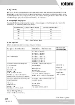
For Ex e d and non-hazardous area variants, loosen the 2
grub screws “L” holding the closed (narrow) cam to the
main SPI shaft.
18.
Slide the closed cam around the main SPI shaft until the
switch is made, then re-tig
hten the grub screws “L” to the
prescribed torque.
19.
The open (wide) cam “M” is designed
so it is possible to
continually signal open for valve positions between 60%
open and fully open.
a.
If this feature is desired, turn the input shaft of
the SPI to the chosen valve position between
60% open and fully open, and follow steps 17
and 18 to set position of the open cam.
b.
If this feature is not required, turn the input
shaft of the SPI until the valve is fully open, and
repeat steps 17 and 18 for the open cam.
20.
Lightly coat the top section of the external diameter of the main SPI shaft
“
G
”
with a suitable grease
and refit the electrical cover onto the main housing, taking care not to damage the central lip seal or
the external diameter O-ring. Secure with the 4 retained screws
“
E
”
and tighten to the prescribed
torque.
21.
Refit the indicator plate to the input shaft, secure with the 4 small screws
“
D
”
and tighten to the
prescribed torque.
22.
Lightly coat the input shaft with a suitable grease (Rotork recommends Fuchs Renolit CLX2 or
equivalent) and mount the handwheel. Secure as appropriate for the handwheel design.
23.
Loosen the 4 small screws
“
F
”
retaining the open / shut plates on the electrical cover enough to allow
the plates to slide over each other.
24.
Turn the handwheel until the valve is fully open.
25.
Position the “OPEN” plate to be in line with the position indicato
r plate, and lightly tighten a single
screw
“
F
”
to prevent accidental movement.
M4 x 8
stainless steel
hex head
screw
I
Figure 6
–
SPI Commissioning: Adjustable Parts for Ex i Variants
K
M5
nyloc nut J
ng
H
Plastic
Setting
Ring
M6 x 10 grub
screw
L
M
Figure 7
–
SPI Commissioning: Adjustable Parts for
Ex e d and Non-Hazardous Area Variants

