background image

4

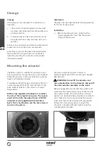
Storage

Storage 

If the actuators are scheduled for installation at a 
later date: 

a.   The actuator should be placed in a clean and 

dry place, and protected from the weather and 
extreme vibration. 

b.   If actuator needs to be stored outside, it must 

be protected from excess moisture, dust, and 
weather. 

Rotork cannot accept responsibility for deterioration 
caused on-site once the covers are removed. 

Every Rotork actuator has been fully tested before 
leaving the factory to give years of trouble free 
operation providing it is correctly commissioned, 
installed and sealed. 

Lubrication 

The gear train has been lubricated during assembly 
for the life of the actuator.

Installation 

a.   Before mounting actuator, verify that the 

torque requirement is less than the output 
torque of the actuator.  

Mounting the actuator 

The ROM actuator is suitable for quarter turn non 
thrust applications. Ensure the valve is secure before 
fitting the actuator, as the combination may be top 
heavy and therefore unstable. 

A suitable mounting flange conforming to ISO5211 
or USA Standard MSS SP101 must be fitted to the 
valve. Refer to label for conformation of output 
flange details. 

ROM can be supplied with adaptors to reduce 
the size of the output drive square. The square 
insert is fitted into the output drive. All ROM 
actuators can be supplied with blank drive 
bush. This is machined to suit the valve stem as 
shown in the picture. 

Actuator to valve fixing must conform to:  
Material Specification ISO Class 8.8, yield strength 
628 N/sq mm. 

 WARNING: Do not lift the actuator and 

valve combination via the Actuator. Always lift 
the valve/actuator assembly via the valve. 

Before engagement, ensure that the actuator and 
valve are in the same position (e.g. closed) and the 
drive spline matches the stem position. Actuator 
position can be determined using the local indicator 
and if necessary can be moved using the manual 
input drive. Secure the actuator with appropriate 
fixing bolts. It may be necessary to adjust the 
stop blots to enable sufficient travel. Ensure the 
mounting bolts are tight.

Summary of Contents for ROM 1/A

Page 1: ...Redefining Flow Control ROM Series Installation Manual Valve Actuators...

Page 2: ...connections 6 Operating by hand 7 Commissioning 8 Troubleshooting 13 Wiring diagram 14 This manual contains important safety information Please ensure it is thoroughly read and understood before inst...

Page 3: ...mechanical installation should be carried out as outlined in this manual and also in accordance with relevant standards such as British Standard Codes of Practice Actuator may start and operate withou...

Page 4: ...or as the combination may be top heavy and therefore unstable A suitable mounting flange conforming to ISO5211 or USA Standard MSS SP101 must be fitted to the valve Refer to label for conformation of...

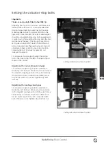
Page 5: ...ng the bolt in reduces movement out increases movement For clockwise closing valves the right hand stop bolt is the closed stop The left is the open stop as shown in the picture Adjustment for non sea...

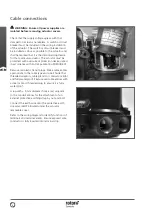
Page 6: ...nce with Rotork publication PUB008 001 Remove red plastic transit plugs Make cable entries appropriate to the cable type and size Ensure that threaded adaptors cable glands or conduit are tight and fu...

Page 7: ...hen the actuator is operated electrically CAUTION With respect to handwheel operation of Rotork electric actuators under no circumstances should any additional lever device such as a wheel key or wren...

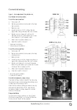
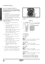
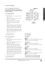
Page 8: ...ow items described below For plastic cam as shown in picture A refer to Type 1 Cam adjustment for plastic cam on page 9 to adjust Cam For metal cam of ROM 1 A as shown in picture B refer to Type 2 Cam...

Page 9: ...n c Remove cover d Locate travel cam 2 TC2 Depressing the cam against the spring will allow the cam to rotate e Rotate cam clockwise until switch operates Note it may be necessary to rotate cam counte...

Page 10: ...m 1 2 3 below 1 Use manual override to turn valve to the fully closed position 2 Make sure the roller of LS2 is touching the cylindrical surface of TC2 3 Case 1 For ROM 1 rotate TC2 clockwise slowly u...

Page 11: ...verride to turn valve to the fully closed position c Remove cover and loosen the TC2 set screw using a 2 5 mm Allen key d Case 1 If the roller of LS2 is touching the cylindrical surface of TC2 rotate...

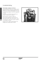
Page 12: ...has slipped out of range Move the valve to the fully closed position and ensure the stop bolts are correctly set Note there are no stop bolts in ROM 1 A Remove the potentiometer mounting screws to re...

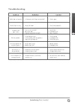
Page 13: ...eats 1 Is the voltage correct 2 Is the valve too tight for operation 3 High working frequency 1 Check voltage 2 Investigate valve 3 Check duty cycle Actuator operates but no valve moment 1 Drive adapt...

Page 14: ...14 Wiring Diagram ROM 1 A 2 3 4 5 6...

Page 15: ...15 Redefining Flow Control Notes...

Page 16: ...For the very latest version release visit our website at www rotork com The name Rotork is a registered trademark Rotork recognises all registered trademarks Published and produced in the UK by Rotor...

Reviews: