


2
CHANGE PHOTO
PHOTO CAN BE
DELETED IF TWO
COLUMNS OF
CONTENTS ARE
REQUIRED
Contents
Section
Page
Health and safety
3
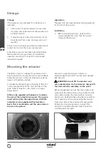
Storage
4
Mounting the actuator
4
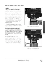
Setting the actuator stop bolts
5
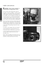
Cable connections
6
Operating by hand
7
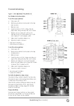
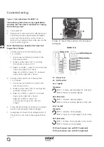
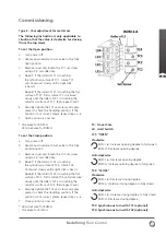
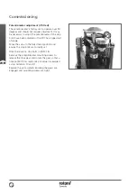
Commissioning
8
Troubleshooting
13
Wiring diagram
14
This manual contains important
safety information. Please ensure it
is thoroughly read and understood
before installing, operating or
maintaining the equipment.
Due to wide variations in the terminal
numbering of actuator products, actual
wiring of this device should follow the
print supplied with the unit.


