6
Cable connections
WARNING: Ensure all power supplies are
isolated before removing actuator covers.
Check that the supply voltage agrees with that
stamped on actuator nameplate. A switch or circuit
breaker must be included in the wiring installation
of the actuator. The switch or circuit breaker must
be installed as close as possible to the actuator and
shall be marked that it is the disconnecting device
for that particular actuator. The actuator must be
protected with overcurrent protection devices rated
in accordance with Rotork publication PUB008-001.
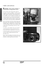
Remove red plastic transit plugs. Make cable entries
appropriate to the cable type and size. Ensure that
threaded adaptors, cable glands or conduit are tight
and fully waterproof. Seal unused cable entries with
a steel or brass threaded plug to ensure it is fully
waterproof.
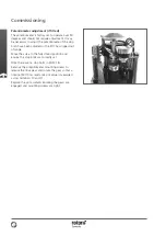
A lug with a 5 mm diameter hole is cast adjacent
to the conduit entries for the attachment of an
external protective earthing strap by nut and bolt.
Connect the earth wire onto the protective earth
screw marked PE located under the actuator
removable cover.
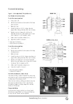
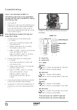
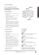
Refer to the wiring diagram to identify functions of
terminals and terminal idents. Ensure exposed wire
conductor is fully inserted into terminal strip.


