Modbus MFU Option Card Installation Manual
72 of 76
Publication PUB091-003-00_0119
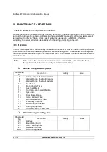
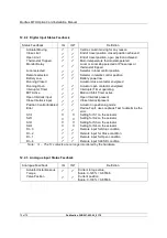
12.4.3 Data Locations
Read Output Status – Function code 01
Write Output Coil – Function code 05 and 15
Location
(Bit)
R/W
Data
Range
0
R/W
Stop command output coil status
0-1
1
R/W
Close command output coil status
0-1
2
R/W
Open command output coil status
0-1
3
R/W
ESD command output coil status
0-1
4
R/W
DO-1 output coil status
0-1
5
R/W
DO-2 output coil status
0-1
6
R/W
DO-3 output coil status
0-1
7
R/W
DO-4 output coil status
0-1
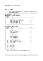
Read Input Status – Function code 02
Location
(Bit)
R/W
Data
Range
0
RO
Actuator moving
0-1
1
RO
Closed limit
0-1
2
RO
Open limit
0-1
3
RO
Thermostat Tripped
0-1
4
RO
Monitor Relay
0-1
5
RO
Local selected
0-1
6
RO
Remote selected
0-1
7
RO
Battery Low
0-1
8
RO
Running Closed
0-1
9
RO
Running Open
0-1
10
RO
Interrupter Timer
0-1
11
RO
MIT Active
0-1
12
RO
Open Interlock input
0-1
13
RO
Close Interlock input
0-1
14
RO
Position control enabled
0-1
15
RO
Error
0-1
16
RO
S1
0
17
RO
S2
0
18
RO
S3
0
19
RO
S4
0
20
RO
DI –3
0-1
21
RO
DI –2
0-1
22
RO
DI –1
0-1
23
RO
DI –4
0-1
Note:
– The ‘S’ contacts are no longer monitored by the hardware
Note:
All data locations listed start from 0, it may be necessary to add an offset to match the
number required for the PLC.

