Modbus MFU Option Card Installation Manual
16 of 76
Publication PUB091-003-00_0119
3.5 Replacing or Fitting a Modbus Module Option Card
The MFU should be replaced or fitted only in a suitable environment. The actuator must be made
electrically safe before opening any covers.
The Modbus card described in this manual contains static-sensitive devices. Suitable
precautions, such as wearing an earthed anti-static wrist strap, should be taken before
handling the card. The card should be kept in an anti-static bag or box while it is not fitted
within an actuator
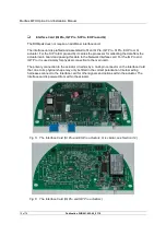
The electrical housing cover should be removed and the existing MFU carefully unplugged from its
main connector. Once removed from the main connector, the wiring loom connectors should be
removed. The replacement board is fitted in the reverse order to removal. The wiring harnesses are
polarised so that only the correct one will fit its mating part on the circuit board.
If the operation is to fit an MFU for the first time then the necessary wiring looms must be added to the
internal wiring harness of the actuator. The actuator wiring diagram shows the connectors and
harnesses used. The wiring harnesses are fitted inside the actuator before attempting to fit the MFU.
Once the looms are in place connect them to the MFU, then fit the MFU to the actuator main board
connector.
Once the module is fitted, the actuator should be re-assembled.
Once power is applied the field unit parameters should be checked and corrected where necessary,
see Section 9.


