


カメラヘッドの向き調整
必要工具
・トルクスレンチ T5:1本
(
同梱
)
・
トルクスレンチ T10(又は六角レンチ):1本
・カメラヘッド位置調整専用のピンセット:1個
(
同梱
)
図2
5
B
2.
1. (6x)
3.
カメラでモニターする領域を決定します。
カメラには広角レンズが装備されていますが、必要とする監
視領域をカバーするためにカメラヘッドを最適な向きに調整
する必要がある場合があります。
カメラのレンズの位置と作業領域(監視したい領域)の中心
を結ぶ線の、水平方向と垂直方向の角度の目安をつけます。
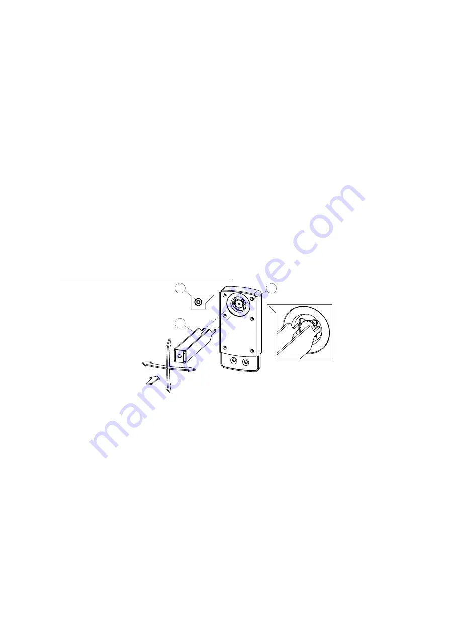
図2に示すハウジングの背面側(レンズ側)の6本のトルクス
ボルトT5
(
A
)
を緩めた状態で、カメラヘッドの向きを調整し
ます。6本のボルトは完全には取外さず、緩めるだけでレン
ズを保持しているボールジョイントによりヘッドの向きを変
えられます。
C
Figure 2
Adjusting the camera head
Required tools
1x
1x
Screw driver Tx 5 (included)
Screw driver Tx10 (or hexagon socket)
Special-purpose tweezers (included)
Determine the workspace area to be monitored by the
camera. The camera is equipped with a wide-angle lens.
It may nevertheless be necessary to appropriately point
the camera in order to monitor the desired area.
Estimate the horizontal and vertical angle between the
position of Rotoclear S3 and the center of the work-
space.
As shown in Figure 2, the camera head is adjusted by
loosening, but not completely removing, the six screws
(a) on the backside (camera side). The ball joint can now
move freely. Use the special-purpose tweezers (B) to
now adjust the camera head as desired. The head can be
tilted horizontally and vertically by approx. 30° each. The
slotted holes (C) are designed for this purpose. Take par-
ticular care to avoid touching and damaging the camera
lens.
Do not to move the camera in another direction as the
arrows indicate. Do not rotate the camera head. The
stream of the camera can be rotated in the settings
menu.
Carefully tighten the screws once the camera is aligned
(torque 0.1 Nm). Be sure to avoid damaging the housing
in the process.
It is good practice to verify the alignment. Do so by
installing the camera as described in section “Startup,
Operations” and connect a WiFi-enabled device directly
with the camera. For this purpose, it is sufficient to
mount Rotoclear with two opposing screws.
Pull off the protective film as soon as the alignment is
completed.
1. Also remove the protective film on the included glass
plate (A) as shown in Figure 3.
2. Position the glass plate in the designated notch (B)
to cover the camera. This permanently seals and
protects the camera against spray water.
A
図
2
に示すように専用のピンセット(B)の先端をボールジョ
イントの長穴(C)に差込み、必要に応じてレンズの向きを調
整します。
レンズは水平方向/垂直方向それぞれ30°だけ角度が振れま
す。この時、カメラのレンズに触れたり、レンズに損傷を与
えないように十分注意して下さい。
レンズの向きの調整は図中の矢印の方向(水平方向/垂直方
向)だけで行って下さい。
(2
軸の組合せで斜めに向けるの
は可能
)
但し、レンズを回転方向にねじるのは絶対に止めて下さい。
カメラが壊れます。
デバイスに表示される画像は、後述の設定画面で回転でき
ます。(0°,90°,180°,270°)
カメラヘッドの向き調整が完了したら、6本のトルクスボ
ルト(A)を慎重に締めていきます。(締付けトルク0.1Nm)
締める過程でハウジングが損傷しないように注意して下さ
い。
調整後は、仮止め状態のままでカメラで映す画面を確認す
る事をお勧めします。
後述の「スタートアップ、操作」の項に記載のようにカメ
ラを取付け、Wi-Fi対応デバイスと接続してカメラの画像
が監視したいエリアと一致しているか(レンズの向きが適
切か)を確認して下さい。
カメラを組み込んだロトクリアS3を機械の窓に取付けて画
像を確認しますが、この時のロトクリアの取付は正規のボ
ルト10本止めではなく2本による仮止めで十分です。
調整
が完了したら、カメラの保護フィルムを外します
。
1、図3に示すように、同梱のカメラ保護用ガラスパネル
(C)から、剥離紙(A)を剥がしてください。
2、保護パネルをハウジングのへこんだ部分(B)に貼付け
て下さい。これにより、カメラを恒久的にシールして、ス
プレー水から保護します。
1x


