6. Refrigerant Pipe Installation
7. Vacuum Drying and Leakage
Checking
7.1 Purpose of vacuum drying
•
Eliminating moisture in system to prevent the phe-
nomena of ice-blockage and copper oxidation.
Ice-blockage shall cause abnormal operation of
system, while copper oxide shall damage
compressor.
•
Eliminating the non-condensable gas (air) in system
to prevent the components oxidizing, pressure fluc-
tuation and bad heat exchange during the operation
of system.
7.2 Selection of vacuum pump
•
The ultimate vacuum degree of vacuum pump shall
be -756mmHg or above.
•
Precision of vacuum pump shall reach 0.02mmHg or
above.
7.3 Operation procedure for vacuum drying
Due to different construction environment, two kinds of
vacuum drying ways could be chosen, namely ordinary
vacuum drying and special vacuum drying.
7.3.1
Ordinary vacuum drying
1.
When conduct first vacuum drying, connect pressure
gauge to the infusing mouth of gas pipe and liquid pipe,
and keep vacuum pump running for 1hour (vacuum
degree of vacuum pump shall be reached -755mmHg).
2. If the vacuum degree of vacuum pump could not reach
-755mmHg after 1 hour of drying, it indicates that there is
moisture or leakage in pipeline system and need to go on
with drying for half an hour.
3. If the vacuum degree of vacuum pump still could not
reach -755mmHg after 1.5 hours of drying, check whether
there is leakage source.
4 . Leakage test: After the vacuum degree reaches
-755mmHg, stop vacuum drying and keep the pressure for
1 hour. If the indicator of vacuum gauge does not go up,
it is qualified. If going up, it indicates that there is moisture
or leak source.
7.3.2
Special vacuum drying
The special vacuum drying method shall be adopted when:
1. Finding moisture during flushing refrigerant pipe.
2. Conducting construction on rainy day, because rain
water might penetrated into pipeline.
3. Construction period is long, and rain water might
penetrated into pipeline.
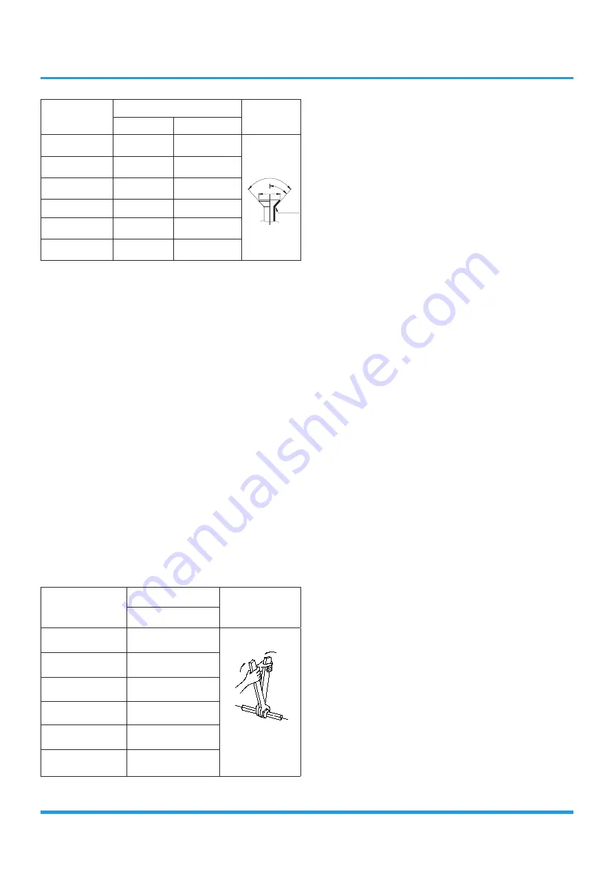
Pipe diameter
(inch(mm))
Flare dimension A (mm/inch)
Flare shape
Min
Max
1/4" (6.35)
8.4/0.33
8.7/0.34
R0.4~0.8
45 °±
2
90°
±4
A
3/8" (9.52)
13.2/0.52
13.5/0.53
1/2" (12.7)
16.2/0.64
16.5/0.65
5/8" (15.9)
19.2/0.76
19.7/0.78
3/4" (19)
23.2/0.91
23.7/0.93
7/8" (22)
26.4/1.04
26.9/1.06
•
After flared the pipe, the opening part must be seal
by end cover or adhesive tape to avoid duct or exog-
enous impurity come into the pipe.
7. Drill holes if the pipes need to pass the wall.
8. According to the field condition to bend the pipes so
that it can pass the wall smoothly.
9. Bind and wrap the wire together with the insulated pipe
if necessary.
10. Set the wall conduit
11. Set the supporter for the pipe.
12. Locate the pipe and fix it by supporter
•
For horizontal refrigerant pipe, the distance be-
tween supporters should not be exceed 1m.
•
For vertical refrigerant pipe, the distance between
supporters should not be exceed 1.5m.
13. Connect the pipe to indoor unit and outdoor unit by
using two spanners.
•
Be sure to use two spanners and proper torque to
fasten the nut, too large torque will damage the
bellmouthing, and too small torque may cause
leakage. Refer the following table for different pipe
connection.
Pipe Diameter
Torque
Sketch map
N.
m(lb.ft)
1/4" (6.35)
15~16
(11~11.8)
3/8" (9.52)
25~26
(18.4~19.18)
1/2" (12.7)
35~36
(25.8~26.55)
5/8" (15.9)
45~47
(33.19~34.67)
3/4" (19)
65~67
(47.94~49.42)
7/8" (22)
75-85
(55.3-62.7)
Summary of Contents for ANERU Series
Page 2: ......
Page 5: ......
Page 6: ...Contents 1 Precautions 2 2 Information servicing For flammable materials 3 Safety Precautions...
Page 12: ...Contents 1 Model Reference 2 2 External Appearance 3 Model Reference...
Page 15: ...Model Reference 4 2 2 Outdoor Unit Single Fan Outdoor Unit Double Fan Outdoor Unit...
Page 18: ...IDU Console 3 2 Dimensional Drawings 16 Drain pipe Hanging arm 195 700 600 210...
Page 21: ...IDU Console 6 6 Air Velocity and Temperature Distributions Discharge Angle 60...
Page 36: ...IDU Compact Cassette 4 2 Dimensional Drawings...
Page 38: ...IDU Compact Cassette 6 4 Service Place...
Page 56: ......
Page 115: ...IDU Super Slim Casstte 54 36k 42k 48k 55k...
Page 118: ......
Page 131: ...IDU Duct 7 6 Fan Performance 12K...
Page 132: ...IDU Duct 8 18K...
Page 133: ...IDU Duct 9 24K...
Page 134: ...IDU Duct 10 30K 36K...
Page 135: ...IDU Duct 11 42K 48K...
Page 136: ...IDU Duct 12 55K...
Page 165: ...IDU Duct 41 12k 18k 24k 30k...
Page 166: ...IDU Duct 42 36k 42k 48k 55k...
Page 178: ......
Page 179: ...35mm 1 38in...
Page 180: ......
Page 256: ...IDU Floor Ceiling 82 36k 48k 55k...
Page 259: ......
Page 267: ...Outdoor Unit 3 Panel Plate B30...
Page 268: ...Outdoor Unit 4 Panel Plate BA30...
Page 269: ...Outdoor Unit 5 Panel Plate CA30...
Page 270: ...Outdoor Unit 6 Panel Plate D30...
Page 271: ...Outdoor Unit 7 Panel Plate X230...
Page 272: ...Outdoor Unit 8 Panel Plate X330...
Page 273: ...Outdoor Unit 9 Panel Plate X430...
Page 274: ...Outdoor Unit 10 Panel Plate E30...
Page 275: ...Outdoor Unit 11 Panel Plate 590...
Page 276: ...Outdoor Unit 12 2 Service Place...
Page 285: ...Outdoor Unit 21 UO70Xo UO90Xo UO100Xo UO100Xo3F...
Page 286: ...Outdoor Unit 22 UO120Xo UO140Xo UO160Xo...
Page 291: ......
Page 292: ......
Page 293: ......
Page 294: ......
Page 295: ...Outdoor unit printed circuit board diagram 17122000044714 17122000048121 17122000046453...
Page 297: ...Outdoor unit printed circuit board diagram 17122000048064...
Page 299: ...Outdoor unit printed circuit board diagram 17122000047742 1 3 4 6 8 9 5 7 10 12 11 2 13...
Page 302: ...Outdoor unit printed circuit board diagram 17122000041841...
Page 304: ...Outdoor unit DC motor driver board diagram 17122000021912 5 6 1 2 3 4...
Page 320: ...3 IDU Installation Duct Connector Connector...
Page 352: ...Product Features 13 Remote LCD Screen Indicators...
Page 549: ......
Page 550: ......
Page 551: ......
Page 552: ...email info rotenso com www rotenso com INSTALLER STAMP...


