background image

3

EN

Index

1. Safety Instructions 

4

1.1. Equipment 

4

1.2. Risks from noise development 

4

1.3. Risks posed by moving parts 

4

1.4. Risks posed by gas emissions 

4

1.5. Risks posed by fuel 

4

1.6. Risks posed by high temperatures 

4

1.7. Risks posed by exhaust gas 

4

1.8. Maintenance intervals 

4

1.9. Disposal of toxic waste 

4

2. Transportation and storage 

5

2.1 Transportation for assembly 

5

2.2. Storage as newdrive 

5

2.3. Prolonged downtime/Storage 

5

2.3.1. From 30 days to 6 months 

5

2.3.2. Longer than 6 months 

5

3. Specification 

6

3.1. Technical data 

6

3.2. Derating chart for operation under different conditions  7
3.3. Performance Curve 

7

3.4. Flange and shaft dimensions 

8

4. Installation 

9

4.1. Preparation 

9

4.2. State of installation site 

9

4.2.1. In- and outtake Ventilation 

9

4.3. Motor mounting 

9

4.4. Exhaust gas system 

9

4.4.1. Mounting the muffler 

9

4.4.2. Information about other exhaust gas systems 

9

4.5. Fuel System 

9

4.6. Coupling 

10

4.6.1. Maximum axial and radial load 

10

4.6.2. Balancing 

10

4.6.3. Direct coupling 

10

4.6.4. Operating with a pulley 

10

4.7. Concluding mechanical installation instructions 

11

4.8. Speed controller 

11

4.8.1. Type “A” – for variable speed 

11

4.8.2. Type “C” – for constant speed 

11

4.9. Electrical installation 

11

4.9.1. Electrical connection (chords) 

11

4.9.2. Starter battery 

11

4.9.3. Circuit diagram of starter-dynamo 

12

4.9.4. Oil-pressure sensor 

12

4.9.4.1. Schematics of oil-pressure sensor-lamp 

12

4.9.4.2. Oil-pressure sensor with magnetic valve 

12

5. Usage 

13

5.1. Components 

13

5.2. Information about engine performance 

13

5.3. Information about starter battery (optional) 

13

5.4. Check-ups before every start-up 

13

5.4.1. Engine oil 

13

5.4.2. Fuel 

14

5.4.3. Fuel system ventilation 

14

5.4.4. Other check-ups 

14

5.5. Start-up 

14

5.5.1 Special information about initial start-up 

14

5.5.2. Starting the engine 

14

5.5.2.1. Hand start (all versions) 

15

5.5.2.2. Electric start (only motor version “E”) 

15

5.5.3 Stopping the engine 

15

6. Maintenance 

16

6.1. Instructions about maintenance 

16

6.2. Precautions 

16

6.3. Starter battery 

16

6.4. Cleaning the crankcase 

16

6.5 Upkeep 

16

6.5.1 Changing the engine oil 

16

6.5.2 Cleaning and exchanging the air filter 

17

6.5.3. Fuel Supply 

17

6.5.3.1. Changing the fuel filter 

17

6.5.3.2. Ventilating the injection system 

17

6.5.3.3. Examining, cleaning the injection nozzle 

17

6.5.4. Proper timing/adjusting the valves 

18

6.5.5. Governing behaviour 

18

6.5.6. Muffler and colours of exhaust fumes 

18

6.5.7. Other 

18

6.5.8. General tightening torque 

19

6.5.9. Engine torque and measured values 

19

6.5.10. Solving electric issues 

19

6.5.10.1 Starter malfunction 

19

6.5.10.2. Battery does not charge 

19

6.6. Maintenance intervals 

20

6.7. Possible errors and their solutions 

21

6.7.1. Engine does not start 

21

6.7.2. Abnormal colour of exhaust gas 

21

6.7.3. Low engine performance 

22

6.7.4. Rough engine run 

22

6.7.5. Engine overheating 

22

6.7.6. Engine suddenly stopps 

22

6.7.7. Abnormal running noise 

22

6.8. List of parts/exploded assembly drawing 

23

6.8.1. Crankcase 

23

6.8.2. Cylinder head 

24

6.8.3. Shafts 

25

6.8.4. Fuel 

25

6.8.5. Flywheel 

26

6.8.6. Electrics 

26

7. Appendix 

27

7.1. Warranty conditions 

27

7.2. Declaration of conformity 

27

Summary of Contents for ED4-0474-5

Page 1: ...Air cooled single cylinder diesel engine ED4 5 series User and maintenance manual EN L1812 version March 2019 ED4 0474 5...

Page 2: ...en necessary Corrected versions are available on our website Should questions come up about the device or its proper handling please contact us before installing or using it All pictures are used as s...

Page 3: ...5 1 Components 13 5 2 Information about engine performance 13 5 3 Information about starter battery optional 13 5 4 Check ups before every start up 13 5 4 1 Engine oil 13 5 4 2 Fuel 14 5 4 3 Fuel sys...

Page 4: ...ediate medical attention is required Do not attempt to vomit after swallowing Should fuel spill over your skin or clothes immediately rinse with soap and water and change your clothes Always keep the...

Page 5: ...ructions Start the motor and let it get to operating temperature about 5 minutes of running the engine Stop the motor and drain the lubricating oil using the drain plug Fill motor protection oil into...

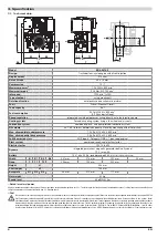
Page 6: ...223 mm Height H 494 mm Shaft height W 155 mm Baseplate G1 G2 G3 95 mm 272 mm 117 mm Net weight 53 kg Sound level 89 dB A 4m 1 Rated maximal power All given information applies to the engine at 0m sea...

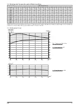
Page 7: ...63 0 57 0 50 3500 0 70 0 70 0 70 0 69 0 66 0 64 0 64 0 64 0 63 0 63 0 61 0 55 0 48 4000 0 66 0 65 0 65 0 64 0 61 0 59 0 59 0 58 0 58 0 58 0 55 0 52 0 46 4500 0 60 0 60 0 60 0 58 0 56 0 54 0 54 0 53 0...

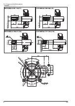
Page 8: ...KW25x88 F2 MOTORWELLE TP26x77 FG2 35 35 86 35 18 8 65 0 2 30 30 65 0 2 14 M8 6H Tiefe 15 1 2 7 165 1 1 4 6 0 8 h 7 0 0 0 4 28 15 8 88 25 0 020 0 041 62 20 15 8 88 25 4 0 0 025 62 28 4 35 77 1 5 26 0...

Page 9: ...ndation must be adequately dimensioned and tor sion resistant It has to be robust enough to absorb vibrations and to maintain alignment The foundation must be chosen so that all mounting feet are laid...

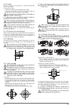
Page 10: ...with the tolerance of the manufacturer Sloppy balancing can lead to vibrations bearing failure or to the shaft breaking Instructions Attach both coupling halves so that a movement is possible with bo...

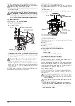
Page 11: ...are also necessary 4 8 2 Type C for constant speed This speed controller is made for fixed speed and is usually used as a speed controller for generators At delivery the engine is set up as follows Ra...

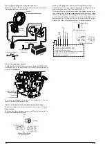
Page 12: ...en there is too little oil A sudden fall in oil pressure cannot be measured Oil pressure sensor Thread 1 8 Closed 0 9bar Open 1 1bar GND over sensor thread on crankcase cover 12V 12V Lamp 4 9 4 2 Oil...

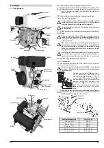
Page 13: ...car battery to jump start the engine first disconnect the starter battery of the motor If the built in battery is completely drained the car battery could load an extremely large current into the star...

Page 14: ...bottom nut During operation no diesel should escape Check this during a test run Reconnect the injection pipe and switch the governor to full speed The motor should start after a few tries The engine...

Page 15: ...y be repeated for a maximum of 3 times then the electric starter has to be left to cool down for at least 15 minutes Contravening can result in damaging the starter and or motor Never start into the r...

Page 16: ...as thoroughly servicing and maintaining the device significantly prolongs the life span of your device Small mistakes can cause huge problems even break the device entirely Here you will find instruct...

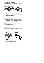
Page 17: ...k cap and take out the fuel filter You can use a needle nose pliers to pull the fuel filter Make sure the gasket and the o ring of the fuel cock are securely set when reassembling After reassembling c...

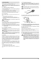
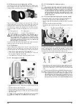
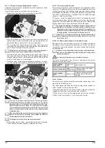
Page 18: ...ideal speed are important These two characteristics disagree with each other Optimal balance is reached when the speed changing causes a 1 time low oscillation This means set up the speed without loa...

Page 19: ...Measure the battery voltage at the starter M8 screw If there is no voltage the battery pole cable is broken Check the voltage at the faston connector of the starter When the start key is set to posit...

Page 20: ...Screws Check all screws including coupled device and the screws of the pedestal Check all screws which are easily accessible Refasten cylinder head and flywheel screws Governing Check easy moving of...

Page 21: ...logged and the motor is getting too little air and therefor has low performance air filter clogged Clean or replace the air filter Clean air filter housing and intake manifold Wrong fuel Remove all fu...

Page 22: ...ogged Clean and check injection nozzle Injection pump not proper mounted or broken Check injection pump position mounting If this is not the solution change the injection pump Governor blocked Speed a...

Page 23: ...104 126 Crankcase gasket 1 ZSPMOT 00443 ZSPMOT 00444 ZSPMOT 00019 127 Main bearing 1 ZSPMOT 00105 ZSPMOT 00106 ZSPMOT 00107 129 Crankcase cover 1 130 Seal ring front 1 standard part 131 Screw 16 stand...

Page 24: ...0128 222 Plate 1 ZSPMOT00709 223 Nut 2 standard part 224 Washer 2 standard part 230 Valve gasket 2 ZSPMOT 00129 ZSPMOT 00130 ZSPMOT 00131 301 Bonnet assy 1 ZSPMOT 00143 ZSPMOT 00143 ZSPMOT 00145 315 W...

Page 25: ...5 504 503 502 510 507 508 508 511 512 505 401 405 407 407 406 408 602 602 601 601 605 603 413 412 Rotek order nr Nr Description pcs ED4 0219 ED4 0306 ED4 0474 118 Needle bearing camshaft 1 standard pa...

Page 26: ...Washer 4 standard part 1411 Recoil starter assy 1 ZSPMOT 00065 ZSPMOT 00006 ZSPMOT 00017 1412 Screw 4 standard part 1501 Gasket 1 1502 Flywheel cover 1 1503 Rubber element 4 1505 Washer 4 standard pa...

Page 27: ...uded from warranty Rotek can not be hold responsible for costs damage direct or indi rect losses including possible loss of profit loss of contract or loss of production which are a result of using th...

Page 28: ...Rotek Handels GmbH Handelsstrasse 4 2201 Hagenbrunn Austria T 43 2246 20791 0 F 43 2246 20791 50 http www rotek at...

Reviews: