


d0
45
3
0
.f
m
MAINTENANCE MANUAL
BRP-Powertrain
Effectivity: 914 Series
Edition 2 / Rev. 0
12-20-00
page 21
January 01/2010
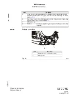
7) Locking the crankshaft
General note
.
NOTES:
The thread bolt for crankshaft locking is part of the stan-
dard tool kit supplied with each engine.
Locking the
crankshaft
The following work procedures are to be accomplished:
Loosen the
crankshaft
After completion of work/check:
WARNUNG
WARNING
Risk of Burns!
Hot engine parts!
Always allow engine to cool down to ambient tempera-
ture before start any work.
Step
Procedure
1
Remove the plug screw (1) M8x20 and sealing ring from the crankcase half
(cyl. 2/4).
2
Turn crankshaft/propeller shaft until the piston of cyl. no. 1 and no. 2 are in
TDC position and lock crankshaft in this position with the thread bolt (2)
part no. 240880.
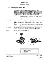
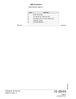
NOTES:
Turn crankshaft for relief the position indification until the trig-
ger boss (3) is between the both trigger coil (4,5) at the po-
sition.
The required recess position of the crankshaft can be addi-
tionally verified by looking through the crankcase recess (6)
with a flash light.
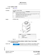
3
Screw the thread bolt (2) into the crankcase. While doing so, move the crank-
shaft to and fro slightly with the ring spanner until the locking screw engages
in the recess (6) of the crankshaft, and tighten to 10 Nm (88.48 in.lb).
Step
Procedure
1
Remove the thread bolt (2) and refit crankshaft plug screw M8x20 (1) along
with a new sealing ring with a torque of 15 Nm (133 in.lb).
2
To check, use wrench 24 mm (15/16 inch.) to rotate the crankshaft at hex.
screw (7) on the magneto side.
Summary of Contents for 914 series
Page 183: ......


