


Installation
Page 18
RES-403
Version 1
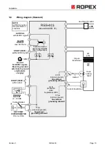
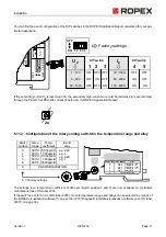
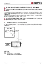
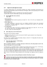
5.11.3 Configuration of the alarm relay
If the plug-jumper is not inserted - or if it is incorrectly inserted - an error message appears when
the controller is switched on (
section 6.12 "Error messages" on page 34).
If the "Alarm output opened by alarm/PC CONFIGURATION" position is selected (as of October 2005), the
behavior of the alarm output can be configured in more detail by means of the ROPEX visualization software
(
see section 6.10 "Diagnostic interface/visualization software (as of October 2005)" on page 32).
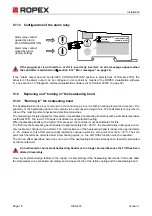
5.12
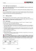
Replacing and "burning in" the heatsealing band
5.12.1 "Burning in" the heatsealing band
The heatsealing band is a key component in the control loop, since it is both a heating element and a sensor. The
geometry of the heatsealing band is too complex to be discussed at length here. We shall therefore only refer to
a few of the most important physical and electrical properties:
The measuring principle applied for this system necessitates a heatsealing band alloy with a suitable temperature
coefficient TCR. Too low a TCR leads to oscillation or uncontrolled heating.
When heatsealing bands with a higher TCR are used, the controller must be calibrated for this.
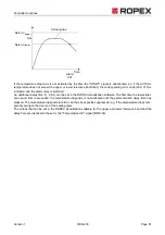
The first time the heatsealing band is heated to approximately 200…250°C, the standard alloy undergoes a once-
only resistance change (burn-in effect). The cold resistance of the heatsealing band is reduced by approximately
2…3%. However, this at first glance slight resistance change results in a zero point error of 20…30°C. The zero
point must therefore be corrected after a few heating cycles, i.e. the AUTOCAL function must be repeated.
The burn-in effect described here does not occur if the heatsealing band has already been thermally pretreated
by the manufacturer.
An overheated or burned-out heatsealing band must no longer be used because the TCR has been
altered irreversibly.
One very important design feature is the copper or silver-plating of the heatsealing band ends. Cold ends allow
the temperature to be controlled accurately and increase the life of the teflon coating and the heatsealing band.
0
5
1
2
3
4
6
7
8
9
Alarm relay contact
opened by alarm/
PC-CONFIGURATION.
Alarm relay contact
closed by alarm.
(factory setting)
CONFIGURATION
ALARM OUTPUT
DE-ENERGIZED / PC
AT ALARM
ENERGIZED
!
!