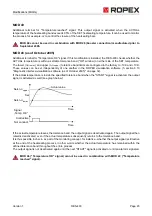
Controller functions
Page 34
RES-403
Version 1
6.12
Error messages
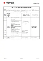
The table below shows how the analog voltage values correspond with the faults that have occurred. It also
describes the fault and the required corrective action.
The error messages are listed in two separate tables for controllers "up to September 2005" and "as of October
2005". The block diagram in section 6.13 "Fault areas and causes" on page 39 permits each fault to be cleared
quickly and efficiently.
13 voltage levels for fault diagnostics appear at the actual value output of all controllers manufactured as of
October 2005. The error messages are differentiated even more finely in the controller. The error codes described
below can be displayed with the ROPEX visualization software (
section 6.10 "Diagnostic interface/visualization
software (as of October 2005)" on page 32) to facilitate troubleshooting.
If the actual value output is evaluated in order to identify an error message - in the higher-level con-
troller, for instance - the tolerance window must be adjusted to prevent it from being incorrectly
interpreted. Please note the tolerances of the actual value output (
page 42).
!


