background image

20 

RONK Automatic Transfer Switch Owner’s Manual

QUICKSTART GUIDE

CONTROLS

MODE SELECTION

This button selects the preferred mode of operation.          to complete the selection press the          button. 

Automatic mode.               This mode allows the module to control the function of the load switching completely automatically. The 
module will monitor the remote start input and mains supply status and once a start request is made, the set will be placed on load.  
Upon removal of the starting signal (or S1supply returns), the module will automatically transfer the load from the generator to the 
mains and remove the genset starting instruction. 

Manual mode.        This mode allows manual control of the ATS functions. Once in this mode the module will send a start request to 
the generator. Breakers can be opened and close using the transfer buttons detailed below. 

Test mode.          Once in Test mode the module will send a start request to the generator and place the set on load or off load 
depending on what is set in the software. The set will remain on load or off load when in this mode.

Start inhibit mode.          This mode is used to provide an over-ride function to prevent the controller from starting the generator in 
the event of a remote start/S1 out of limits condition occurring. 

Prohibit return.             This mode is used to prevent the module from loading  S1 even though  S1 has returned.

DISPLAY

LOAD SWITCHING CONTROL

Two fascia mounted buttons are provided for load switching operation when in manual mode. These buttons are enabled/disabled in 
the modules PC configuration Suite so refer to your configuration file to ensure the configuration has enabled the buttons.

NOTE:

Icons only apply when display mode in the software program is set to `icons`.

This button changes between the various pages About, Status, Instrumentation, Alarms, Event Log, LCD Indicators

This buttons scrolls through the items in the currently displayed page.

Pressing this button when the S1 is on load will open the S1 load switch.

Pressing this button when S2 is on load and S1 is healthy, will open S2 load switch, wait for the duration of the transfer delay,  

then close the S1 load switch.

Pressing this button when S2 is on load will open the S2 load switch.

Pressing this button when the S1 is on load and S2 is available, will open the S1 load switch, wait for the duration of the transfer 

delay, then close S2 load switch.

Summary of Contents for 100-600 AMP

Page 1: ...OWNER S INSTALLATION MANUAL 100 600 AMP RONK Automatic Transfer Switch...

Page 2: ...plain and or exemplify a product service or maintenance improvement We reserve the right to make any change at any time without notice Some images may vary depending upon which model is shown ALL RIGH...

Page 3: ...e 8 SPECIFICATIONS 9 RONK ATS 100A 200A 400A 600A Specifications 9 INSTALLATION AND WIRING 10 General Information 10 Mounting Location 10 Mounting Requirements 10 Recommended Upstream Protection 11 Po...

Page 4: ...anual Transfer 21 400A Manual Transfer 21 600A Manual Transfer 22 MAINTENANCE 23 Recommended Maintenance 23 Maintenance 23 DRAWINGS 24 100A 200A 240V Schematic 24 400A 240V Schematic 25 400A 480V Sche...

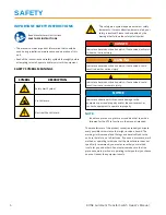
Page 5: ...efore use Refer to the installation section of this manual for instructions on installation procedures Only licensed electrical contractors should install an ATS Installations must comply completely w...

Page 6: ...ion in the manner intended The manufacturer of this product cannot reasonably anticipate every possible circumstance that might involve a hazard The warnings in this manual and the tags and decals aff...

Page 7: ...ocution Do not touch bare wires Do not use equipment with worn frayed bare or otherwise damaged wiring Do not handle electrical cords while standing in water while barefoot or while hands or feet are...

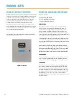
Page 8: ...the enclosure Care should be taken to always protect the equipment from impact Do not remove the protective packaging until the equipment is at the installation site and ready to be installed A shipp...

Page 9: ...x 6 ATS40012 W04 1 400 240 181 lbs 48 x 30 x 10 ATS40014 W04 1 400 480 203 lbs 48 x 30 x 10 ATS40032 W04 3 400 240 188 lbs 48 x 30 x 10 ATS40034 W04 3 400 480 210 lbs 48 x 30 x 10 ATS60012 N06 1 600...

Page 10: ...er FDC 150 A Eaton Cutler Hammer QCHW 125 A Eaton Cutler Hammer FCL 100 A Eaton Cutler Hammer FB 100 A SQUARED D FI 100 A V22 1 200 240 10 kA 0 025 Seconds 22 kA Siemens FXD 250 A Siemens NFK 250 A SQ...

Page 11: ...an the circuit breakers with the recommended ratings given above may cause improper operation of the switch WARNING Low voltage wire cannot be installed in the same conduit as power voltage wiring It...

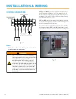
Page 12: ...he remote start stop connections of the generator to allow automatic starting These are N O dry contacts 8A 35 Vdc Max An optional customer supplied test switch may be installed by the customer using...

Page 13: ...s automatic start controller When the ATS controller senses that the generator has started and is within acceptable limits the transfer switch will wait until the utility to generator time delay Para...

Page 14: ...me and day when the battery is re applied SCHEDULER The DSE331 scheduler is the feature that sets the exercise timer for the Automatic Transfer Switch and the generator set The ATS comes from the fact...

Page 15: ...e 240V switches are usable on 208V systems See manual for instructions to change parameters TIME DELAY FUNCTION SETTING LINE Transient 2 Seconds Engine Start 13 Seconds Transfer LINE to AUXILIARY 21 S...

Page 16: ...provides a quick start guide to the module s operation for DSE controller 331 MODE SELECTION OPERATION NOTE For further details see the section entitled MODE SELECTION elsewhere in this manual Press...

Page 17: ...LCD display until the user selects a different page or after an extended period of inactivity the module will revert to the status display When scrolling manually the display will automatically return...

Page 18: ...ch Owner s Manual QUICKSTART GUIDE INSTRUMENTATION The instrumentation page contains the following information S1 Voltage L N S1 Voltage L L S1 Frequency S2 Voltage L N S2 Voltage L L S2 Frequency Bat...

Page 19: ...Switch Fail Alarm The Switching device has failed to operate Failed to Start The engine has not fired after the preset number of start attempts Failed to Stop The module has detected a condition that...

Page 20: ...mode is used to provide an over ride function to prevent the controller from starting the generator in the event of a remote start S1 out of limits condition occurring Prohibit return This mode is use...

Page 21: ...ovable lever handle is used to transfer the mechanism The transfer switch is in the utility position when reference A on the contactor is set to the ON position and reference B is set to the OFF posit...

Page 22: ...h Trip using an object such as a screwdriver to open the utility poles 2 Set the removable handle on M and operate in the UP direction while pushing select with the screwdriver To transfer from Genera...

Page 23: ...ation for possible safety hazards Inspect mounting location for any safety or fire hazards Inspect for dirt wiring damage and mechanical damage Inspect the transfer switch for loose hardware Check all...

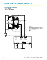
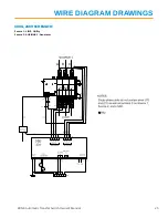
Page 24: ...24 RONK Automatic Transfer Switch Owner s Manual WIRE DIAGRAM DRAWINGS 100A AND 200A SCHEMATIC Source 1 LINE Utility Source 2 AUXILIARY Generator...

Page 25: ...RONK Automatic Transfer Switch Owner s Manual 25 WIRE DIAGRAM DRAWINGS 400A 240V SCHEMATIC Source 1 LINE Utility Source 2 AUXILIARY Generator...

Page 26: ...26 RONK Automatic Transfer Switch Owner s Manual WIRE DIAGRAM DRAWINGS 400A 480V SCHEMATIC Source 1 LINE Utility Source 2 AUXILIARY Generator...

Page 27: ...RONK Automatic Transfer Switch Owner s Manual 27 WIRE DIAGRAM DRAWINGS 600A 240V SCHEMATIC Source 1 LINE Utility Source 2 AUXILIARY Generator...

Page 28: ...28 RONK Automatic Transfer Switch Owner s Manual WIRE DIAGRAM DRAWINGS 600A 480V SCHEMATIC Source 1 LINE Utility Source 2 AUXILIARY Generator...

Page 29: ...licable For example warranty service would not apply if equipment damage occurred because of misuse lack of routine maintenance shipping handling warehousing or improper installation Similarly the war...

Page 30: ...30 RONK Automatic Transfer Switch Owner s Manual NOTES...

Page 31: ...RONK Automatic Transfer Switch Owner s Manual 31...

Page 32: ...106 E State Street Nokomis IL 62075 800 221 7665 www ronkelectrical com...

Reviews: