background image

NEXUS CALL SYSTEM 

by Rondish


P47


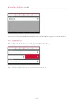
If you want to change how the alarm is displayed you can just tap on the entry again to make amendments. 
 

3.4.3  Delete Device 

If you need to remove something from memory, swipe left over the device. 


Nexus will then prompt you to confirm or cancel the device removal 


Summary of Contents for Nexus Call System

Page 1: ...Nexus Call System User Instructions V2 3 0 August 2022 ...

Page 2: ...ardware 18 2 1 2 Registering Nexus 22 2 1 3 Activating Deactivating Kiosk Mode 22 2 2 Configuring a Repeater Network 23 2 2 1 Network ID 24 2 2 2 Frequency Channel 24 2 2 3 Target Address 25 2 2 4 Data Rate 25 2 2 5 Repeater Address 25 2 2 6 Programming a Signal Hop 27 2 3 Call Points 28 2 4 Over Door Lights 29 2 5 DoorWatcher 31 2 5 1 DoorWatcher Settings 31 2 5 2 Adding DoorWatcher to Nexus 32 2...

Page 3: ... Alarm Screen 43 3 3 1 Display Details 43 3 3 2 Admin Reset 44 3 4 Device Management 45 3 4 1 Add New Device 46 3 4 2 Device Location 46 3 4 3 Delete Device 47 3 5 Event Log 48 3 6 Settings 49 3 6 1 Change Settings 49 3 6 2 Backup Restore 50 3 6 3 Export Log 50 3 6 4 Network Settings 51 3 6 5 Target IP Address 51 3 6 6 Mobile Phone Provisioning 51 3 6 7 Messaging Settings 51 4 MAINTENANCE 52 4 1 B...

Page 4: ...NEXUS CALL SYSTEM by Rondish P4 ...

Page 5: ...active at the same time the three highest priority events will be shown and lower priority calls will display as events are reset or can be seen by scrolling down the alarm screen All events are logged with a record of event location call type time of trigger and duration Optional Over Door lights show Call Bath or Emergency status Each light has an internal buzzer with adjustable volume and can r...

Page 6: ...le remote corridor displays and or paging Ethernet port allows network of multiple stations NCON 11 Junction Box Includes TVB 21 Includes GP2009TR Connect DON 30 or ZP 01 M to establish a wireless network for your facility Surge protection and watchdog functionality to restart Nexus if system becomes unresponsive Connects to touch screen monitor through USB connection DON 30 Receiver Dongle Links ...

Page 7: ...on for patient access from the bed RJ10 plug connects with WCP 11C USB break connection Includes wall mount bracket and screws WCP 11 Bathroom Call Point Call and reset buttons Pull cord with dual triangles Includes mounting screws Replaceable CR2477 lithium batteries Back plate available BP 01 to cover 1 gang back boxes Low battery indication Rated IP65 NEC 05 Wireless Patient Handset Call and re...

Page 8: ...removable clasp Triggers alert on DMS 21 if area matches Low battery indication Rated IP67 NGM 21 CordFree Bed Monitor Room controller for integrated falls management system Pause reset alarms Works with bed chair floor sensormats Motion sensor and door window compatible Uses 3 x AA alkaline batteries Low battery indication TM 11 V3 Transmitter Module Insert into Cordless sensorpad or floor mat to...

Page 9: ...rable and long lasting Low battery indication from TM 11 transmitter module CMAT 02 Cordless Floor Sensormat Triggers alarm when stepped upon Paired with NGM 21 monitor Durable and long lasting Low battery indication from TM 11 transmitter module PIR 21 Motion Sensor Narrow angle detection for bedside use Paired with NGM 21 monitor ...

Page 10: ...rs or Android phones Receiving options are available to cover buildings of various sizes Signals are brought into the Android device using a Receiver Dongle DON 30 for smaller areas or Master Controller and Network Repeaters ZP 01 S which relay the call points and sensory devices status When using Network Repeaters signals can be hopped from one repeater to another to further extend the wireless c...

Page 11: ...ablet NDP 21 Nexus Control Box TVB 21 or Nexus Junction Box NCON 11 When used as a range extender the ILB 21 transmitter uses LoRa on a separate 400MHz channel to the calling device When connecting the ILB 21 you can trigger a range by touching a magnetic key to the program point this reduces the signal by 3bB to ensure the connection is secure The open air ranges of the devices are shown on the d...

Page 12: ...its allowing multiple floors or a campus of buildings to be covered Example Multi floor building Up to 3 hops can be used on the system and using the RSSI readings viewable through the Event log on Nexus this can be optimized for the best layout There may be a bit of trial and error to achieve the best RSSI levels by changing the target address and seeing if the RSSI level is higher or lower You w...

Page 13: ...r units and test at the extremes of that particular zone If your calling device can be received by the tester at the proposed install location you can be confident that it will reliably work when a more sensitive ZP 01 S is used for the actual installation For smaller facilities the ILB 21 Over Door Lights can serve as the repeaters the TTEST 01 can be used for surveying these sites if necessary M...

Page 14: ...nstallation positions for the ZP 01 S repeater units you can visit the site with your map and test out a few of the locations with the Pegasus range tester Place a WCP 11 at the furthest distances from the proposed ZP 01 S location and test the Pegasus can receive the signal If the Pegasus tester will receive alarm and reset signals you can be confident about the signal reliability into a ZP 01 S ...

Page 15: ...programmed to hop through a ZP 01 S with a higher RSSI reading for the most reliable performance You are allowed to hop through 2 x ZP 01 S units 3 hops Once the network is optimized you can start to install call points or other alarm devices throughout the building The main thing to ensure is that the units have different ID codes and that the site code is set correctly if applicable Once the WCP...

Page 16: ...ce Test all units for call and reset It is important to be methodical in this testing and keep good records so it is recommended to make a matrix of test results to ensure all units are tested and in good order Check all the worst case positions to ensure calls can be received The test procedures are similar to the ZP 01 S except the range to an ILB 21 Over Door light is more limited requiring a d...

Page 17: ...k ID and Channel 3 Program ZP 01 S Repeaters to use the same Network and Channel selected at ZP 01 M Master Controller Refer to section 2 2 for details When all Repeaters in the network are initialized by the Master power up or connection check the RSSI values shown in the Event Log Rondish recommends programming a signal hop if recorded RSSI values are below 100 4 Add and mount call points Sectio...

Page 18: ...ill allow the user to interface with Nexus using a touch screen or wireless keyboard mouse Nexus Rugged Tablet NDP 21 The Rugged Tablet comes with a docking station that allows convenient placements on a nurse desk The back of the docking station includes three USB connections allowing a DON 30 or ZP 01 M to connect a network and a GP2009TR paging transmitter to signal paging signals The ethernet ...

Page 19: ...n 2 5 3 Setup Connect the power adapter provided Connect with HD monitor using HDMI cable Connect Bluetooth keyboard and mouse in Setting Connected Devices Pair new devices then follow the instruction Insert DON 30 or ZP 01 M to launch Nexus Disable AC Lost Low battery Warning is turned OFF in the Settings menu Power input HDMI Computer monitor Ethernet to LAN for database Audio out external speak...

Page 20: ... can be connected to computer monitors of various sizes through an HDMI cable and a GP2009TR transmitter for messaging The NCON 11 includes power handling surge suppression fuses regulators with outputs for the various items AC lost and battery low detection and a hardware watchdog to reset the system in the unlikely event of a system crash For Master Station we recommend a touchscreen for ease of...

Page 21: ...NEXUS CALL SYSTEM by Rondish P21 ...

Page 22: ...xus pre installed with a registered software license for your organization If you are loading Nexus onto a device not purchased from Rondish you will be prompted to enter a registration key the first time Nexus is launched The email address and password used for the software registration will allow you to update Nexus as new features are implemented See Section 4 2 for details 2 1 3 Activating Dea...

Page 23: ...k the Home Screen will display how many are included within the network and whether they are currently active In the example below there are five repeaters in Nexus memory but only two are currently detected To program each ZP 01 S you must set several parameters each of which should be consistent with what you have set on the ZP 01 M master unit Section 3 6 4 1 Set Network ID 2 Set Frequency Chan...

Page 24: ...works to operate on the same site Adjust the Address rotary switch to the required Network ID 0 3 factory default 0 Press the T SW button once and the Tx Rx LED will flash once to accept the input 2 2 2 Frequency Channel Using the rotary switch at Address to set a new digit and press T SW button to confirm the setting The table below shows the specific frequencies of each channel Channel EU Freq A...

Page 25: ... S where you will relay the signal See Section 2 2 6 2 2 4 Data Rate Make sure to set this to 0 for Nexus 2 0 and higher 2 2 5 Repeater Address This tells the ZP 01 M where to find this particular repeater The ZP 01 S address 0 47 must be unique within the system so it can be individually called by the Master and Call Points The ZP 01 S unique address is set by adjusting the rotary and DIP switche...

Page 26: ... Switch Positions 1 OFF 2 OFF 1 ON 2 OFF 1 OFF 2 ON 0 0 16 32 1 1 17 33 2 2 18 34 3 3 19 35 4 4 20 36 5 5 21 37 6 6 22 38 7 7 23 39 8 8 24 40 9 9 25 41 A 10 26 42 B 11 27 43 C 12 28 44 D 13 29 45 E 14 30 46 F 15 31 47 Example To set a ZP 01 S Address to 18 Set the rotary switch to 2 Set DIP1 to ON Set DIP2 to OFF Power down the ZP 01 S and reboot Check RSSI value in Event log ...

Page 27: ...signal down the corridor instead of trying to penetrate through several walls When planning the network if your facility good locations for the Network Repeaters are at corridor intersections This allows signals to pass down unobstructed hallways instead of penetrating through walls that can weaken or block the signal Each repeater can cover a radius of 25m for the purposes for site planning so if...

Page 28: ...ries pre installed You will need to change these periodically based on usage Step 2 Add to Nexus Refer to Section 3 4 for how to pair and rename a call point Press the Call button to send the Device ID to the system Step 3 Mounting Use the call point to mark the position of the screw holes on the wall Drill guide holes before screwing the call point into place Step 4 Connect Handsets A similar pro...

Page 29: ...battery life no alarms is more than 18 months Step 2 Select settings Remove front lens using a 2mm flat head screwdriver and select light settings The dip switches control whether the ILB 21 will forward alarms to a central monitor unit The buzzer has maximum volume pf 108dB and can be silenced Switch 1 far left Call Forward On Off Controls whether alarms from paired devices are forwarded Switch 2...

Page 30: ...the Program button on the back of the indication light The red and white sections will both flash three times to indicate the light is ready for operation Step 6 Secure mounting plate Screw the plastic mounting plate to the wall where you will want to locate the ILB 21 Make sure the plate is secured before mounting the light Step 7 Mount the light Snap the ILB 21 onto the mounting plate You will h...

Page 31: ... Management Section 3 4 Remove the end cap of a DMS 21 sensor and pull out the PCB to access switches and to program the sensor Switches Basic Setup Volume Set switch to Hi Lo Off Detection distance Set to Short Med Long Extension Set as Primary Secondary Night mode Programming Advanced Setup Enter programing by holding the magnetic button for 3s Select the value of each parameter using the rotary...

Page 32: ...ration whether a tag is present or not To escort a resident through a door trigger Reset before opening the door The caregiver has 15s to open the door at which point you will have this amount of time to pass through and close the door before triggering an alert Setting Open Time 0 Indefinite 1 15s 2 25s 3 35s Default 4 45s 5 55s 6 65s 7 75s 8 85s 9 95s 2 5 2 Adding DoorWatcher to Nexus Add monito...

Page 33: ...NEXUS CALL SYSTEM by Rondish P33 2 5 4 Activate Patient Tags 2 5 5 Adjust Detection Distance Default detection is 1m ...

Page 34: ... sensormats Door window sensors Motion sensors 2 6 1 Adding Monitors to Nexus Setup procedure Add bed monitor to Device Management by pressing the Reset button Section 3 4 Synch room sensors to NGM 21 Mount sensors and monitors 2 6 2 Synch Sensory Devices with Monitor Press Program button on back of NGM 21 to enter sensor pairing Trigger sensorpad or other device to add into memory Re enter pairin...

Page 35: ... other areas but still see urgent events Each Nexus Station is assigned a Station ID and Call Escalation is flexible to suit different cases Escalation criteria for each Remote Display can be configured for emergency and or cardiac alarms as shown in an example below In this setup there are four nurse stations each of which is locally managed for basic calls Unanswered and emergency calls will be ...

Page 36: ...tered on 450 375MHz and should be kept within a band between 446 375MHz and 454 375MHz The configuration screen for GP2009TR is shown below with default settings TX Frequency Pager system communication frequency 450 375 default RX Frequency Pager system communication frequency 450 375 default Assign a 2 digit Nexus Station ID for each Nexus terminal The Station ID must be unique for each station S...

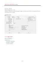
Page 37: ...e Disable Repeater Disable if you would like paging messages to be repeated at intervals you can adjust this here Avoid signal conflict Enabled GP2009TR Settings 2 7 3 Pager Setup Refer to GP2009TR_UI Default settings Frequency 450 375MHz Baud Rate 1200mbs Capcode 1234567 ...

Page 38: ...m Rondish will be pre configured with a suitable software Just connect a GP2009TR along with a monitor using an HDMI cable and alarms will display in a similar format as the Nexus Alarm Screen Section 3 3 If you are using a computer monitor connect a mouse to configure the Remote Display ...

Page 39: ...ation ID e g 1 for Station ID 01 12 for Station ID 12 etc and select the type s of calls this remote display should pick up If additional Station IDs should display add these as a separate task Double click or double tap on the nurse icon to enter Remote Display configuration The chain icon indicates this display is connected with the Master Station If you have lost connection this will appear in ...

Page 40: ... to be used for receiving and acknowledging messages Requires internet connection Turn Mobile Phone messaging ON requires Nexus Mobile license Tap on Mobile Phone Provisioning Scan the QR code using your Android mobile phone If additional Station IDs should display add these as a separate task Make sure to Save the tasks the final column should have a green checkmark ...

Page 41: ...er 3 1 Behavior Table The table below summarizes how Nexus interprets and displays signals from various devices Device Alarm Trigger Alarm Type Nexus Display Over Door Light Cancel Alarm by WCP 11C Single press Call Yellow 10s beep intervals Red Reset on WCP 11C WCP 11C Double press Emergency Red Rapid beeping Alternating Red White Reset on WCP 11C NEC 12 Press button Call Yellow 10s beep interval...

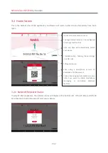
Page 42: ...one camera to download a FAQ document Product licensing key information is shown here if you want to enable smartphone messaging or centralized database features 3 2 Home Screen This is the default view of the application and Nexus will return to this screen after alarms have been reset 3 2 1 Network Repeater Status If using ZP 01 S repeaters the network status will display at the bottom left If t...

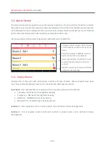
Page 43: ...Nexus will automatically revert to the Home Screen after several seconds Color band this indicates the alarm priority with a time stamp shown on the left side Code Blue BLUE band 0 25s high low beeping Emergency RED band 0 5s high low beeping Bathroom AMBER band 4s beep interval Standard Call YELLOW band 10s beep interval Location 1 this is typically a room or ward number and is defined in Device ...

Page 44: ... Low battery Priority 5 A bed monitor displays when pairing the device to Nexus so the software can provide low battery and device lost alerts During an alarm Nexus will display either a bed chair sensor or floor type alarm 3 3 2 Admin Reset There may be times when an event needs to be cleared from the central display panel This can be achieved by a long press on the event and entering the Admin P...

Page 45: ...es can be added or deleted from Nexus while in this mode Selecting Full Access will prompt the user to first enter the 6 digit PIN for access After doing so they will be able to add delete devices or rename existing devices in memory If a PIN has not been set in the Settings tab the default is 123456 3 4 Device Management This tab is where you add delete devices from Nexus and define how each shou...

Page 46: ...his device in memory it will create a new entry with the 6 digit device ID device type and notification that new hardware has been detected If Nexus already recognizes a device that is triggered while in Device Management it will exit to the Alarm Screen as if a patient has normally triggered an alarm This ensures the call system continues to function if a patient needs help 3 4 2 Device Location ...

Page 47: ...o change how the alarm is displayed you can just tap on the entry again to make amendments 3 4 3 Delete Device If you need to remove something from memory swipe left over the device Nexus will then prompt you to confirm or cancel the device removal ...

Page 48: ...ours will be stored in a data file that can be accessed by exporting and opening using Excel or the complete log can be accessed by tapping the screen seven times Your response time is logged as the duration between an alarm triggering and being reset Refer to Section 3 6 3 for instructions on how to export the data log Users with a Nexus Pro license will have the ability to connect multiple Nexus...

Page 49: ...fication Nexus AC Lost Low Battery Warning Set to enable AC Lost Low Battery Warning Data Pager Enable to configure Data Pager system Disable to configure Remote Display system Mobile Phone Messaging Enable to use mobile messaging 3 6 Settings The Settings tab is where you will set the default name to display on the Home screen change the Admin PIN or export the data log Pressing this tab requires...

Page 50: ...epeaters are connected Section 3 6 4 Network ID Channel Gateway ID Update makes changes take effect 3 6 2 Backup Restore After programming your system the settings and Event log can be saved to a download folder and later exported to a USB drive This allows the programming to be restored on a second panel if the primary unit goes down Nexus will remind you periodically to back up the system 3 6 3 ...

Page 51: ...ust be matched by ZP 01 S network repeaters used at your facility These are covered in Section 2 2 3 6 5 Target IP Address This option will appear if you have a Nexus Pro license By connecting the Nexus Station with a LAN the alarm details will be sent in real time to a central database 3 6 6 Mobile Phone Provisioning The slider can be activated if you have a Nexus Mobile license By activating thi...

Page 52: ...set to silent alarm duration is 1min each and signal bump function turned ON WARNING Risk of explosion if battery is replaced by an incorrect type Replace only with the same or equivalent type CAUTION Lithium batteries should not be disposed of with normal household waste For disposal or recycling instructions please contact your local authorities 4 2 Lost Device Detection Nexus will display any f...

Page 53: ...ving the Nexus tablet to a different location Dongle not receiving LEDs flash but nothing happens on the screen Disconnect and reconnect the dongle Re start the NDP 21 TVB 21 AC Lost warning keeps showing up If using a TVB 21 to operated Nexus you may need to disable the AC Lost Low Battery Warning in the settings menu Disabling this warning is not recommended for everyday use with a tablet Audibl...

Page 54: ...e in which case the user will be required to correct the interference at his own expense The individual device complies with part 15 of the FCC Rules Operation is subject to the following two conditions 1 The device may not cause harmful interference and 2 the device must accept any interference received including interference that may cause undesired operation RF exposure statements 1 The Transmi...

Reviews: