


User Manual of Network Camera
83
25 s, 30 s or not limited.
Post-record: The time you set to stop recording after the scheduled time or the
event. For example, if an alarm triggered recording ends at 11:00, and the
post-record time is set as 5 seconds, the camera records until 11:00:05.
The Post-record time can be configured as 5 s, 10 s, 30 s, 1 min, 2 min, 5 min
or 10 min.
Overwrite: Select Yes, and then the record files will be overwritten when the
HDD becomes full. Otherwise, the recording will stop when the HDD
becomes full.
Recording Stream: Main stream, Sub Stream and Third Stream are selectable
for recording. When you select sub-stream, you can record for a longer time
with the same storage space.
Note:
The record parameter configurations vary depending on the camera model.
4.
Click
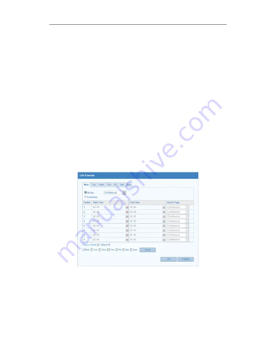
Edit
to edit the record schedule.
Figure 7-6
Record Schedule
5.
Choose the day to set the record schedule.
(1)
Set all-day record or segment record:
If you want to configure the all-day recording, please check the
All Day
checkbox.
If you want to record in different time sections, check the
Customize
Summary of Contents for RBOF2-1W
Page 1: ...9 Network Camera User Manual...
Page 88: ...User Manual of Network Camera 87 Figure 7 8 Snapshot Settings...
Page 106: ......