background image

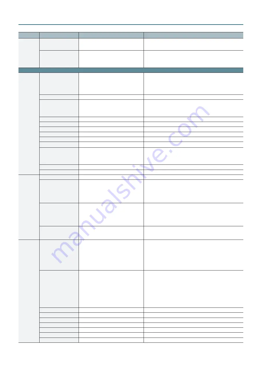
Menu List (Setup Screen)

3

Category

Setting item

Value

Explanation

VFX

EFFECT PATTERN

OFF

, NEGATIVE, EMBOSS, COLORIZE, COLOR 

PASS, POSTERIZE, SILHOUETTE, MONOCOLOR, 

FINDEDGE

This sets the filter effect applied to the main output video. When this is set to 

“OFF,” no effect is assigned.

VALUE

0

–127

This adjusts the amount of effect applied. Setting this to “0” turns off the 

effect.

*  Pressing the [VIDEO FX/KEY LEVEL] button displays the “VIDEO FX” 

shortcut for “VALUE” at the bottom of the screen.

Page 2/3

KEY

KEY SOURCE CH

OFF, CH1–

CH4

, STILL 

This specifies the channel for the video displayed in the foreground during 

key compositing. 
Setting this to “STILL” performs key compositing using a captured still image 

or a still image sent from VR-4HD RCS dedicated software.
When set to “OFF,” operating the [KEY] button has no effect.

KEY TYPE

CHROMA

, LUMI

This sets the key type (chroma key or luminance key) for key compositing.

CHROMA KEY LEVEL

0–

64

–255

This adjusts the degree of extraction (transparency) for chroma key.

*  Pressing the [VIDEO FX/KEY LEVEL] button displays, at the bottom of the 

screen, the “KEY LEVEL” shortcut for either “CHROMA KEY LEVEL” or “LUMI 

KEY LEVEL,” according to setting for “KEY TYPE.”

CHROMA KEY GAIN

0

–255

This adjusts the degree of edge blur for chroma key.

CHROMA KEY COLOR

BLUE

, GREEN

This sets the extraction color for chroma key.

CHROMA KEY HUE WIDTH

-127–

0

–127

This adjusts the hue width (range) for chroma key.

CHROMA KEY HUE FINE

-127–

0

–127

This adjusts the center position of the hue for chroma key.

CHROMA KEY SAT WIDTH

-127–

0

–127

This adjusts the saturation width (range) for chroma key.

CHROMA KEY SAT FINE

0

–255

This adjusts the center position of saturation for chroma key.

LUMI KEY LEVEL

0–

64

–255

This adjusts the degree of extraction (transparency) for luminance key.

*  Pressing the [VIDEO FX/KEY LEVEL] button displays, at the bottom of the 

screen, the “KEY LEVEL” shortcut for either “CHROMA KEY LEVEL” or “LUMI 

KEY LEVEL,” according to setting for “KEY TYPE.”

LUMI KEY GAIN

0

–255

This adjusts the degree of edge blur for luminance key.

LUMI KEY COLOR

BLACK

, WHITE

This sets the separation color for luminance key.

SPLIT

PATTERN

V. CENTER

, H. CENTER, V. STRETCH, H. STRETCH

This sets the split composition pattern assigned to the [SPLIT] button.

A-CENTER

0–

50

–100 %

This is applied when “PATTERN” is set to “V. CENTER” or “H. CENTER.”


5

When at V. CENTER
This adjusts the horizontal position of the video displayed on the left.


5

When at H. CENTER
This adjusts the vertical position of the video displayed above.

B-CENTER

0–

50

–100 %

This is applied when “PATTERN” is set to “V. CENTER” or “H. CENTER.”


5

When at V. CENTER
This adjusts the horizontal position of the video displayed on the right.


5

When at H. CENTER
This adjusts the vertical position of the video displayed below.

PREVIOUS SELECT

OFF

, ON

When set to “ON,” the previously selected channel is selected automatically 

when the [SPLIT] button is pressed.

*  Only the channel displayed to the right or below is automatically selected.

VIDEO OUT

OUTPUT RESOLUTION

AUTO

, 480/576i (*1), 480/576p, 720p, 1080i (*1), 

1080p, 640 x 480, 800 x 600, 1024 x 768,  

1280 x 768, 1280 x 1024, 1366 x 768, 1400 x 1050, 

1600 x 1200, 1920 x 1200

This specifies the output format of the main output video (HDMI OUT 

connector or RGB/COMPONENT output connector).
When this is set to “AUTO,” the output format follows the setting made for 

“SYSTEM FORMAT” (p. 4).
(*1) The “480/576i” and “1080i” formats are supported for HDMI output only.

When the setting is “480/576i” or “1080i,” no video is output from the 

RGB/COMPONENT output connector.

SCALING TYPE

FULL

, LETTERBOX, CROP, DOT BY DOT

This sets the scaling type for the main output video.
FULL:  

This always displays the picture expanded to full screen, 

irrespective of the aspect ratio of the input video.

LETTERBOX:   This enlarges or reduces the incoming video to a full-screen 

view while keeping the aspect ratio unchanged.

CROP:  

This enlarges or reduces the incoming video so that the output 

picture has no blank margins while keeping the aspect ratio 

unchanged. Video extending beyond the borders is cut off.

DOT BY DOT:   This performs no scaling.

OUTPUT H. POSITION

-1920–

0

–1920

This adjusts the horizontal position of the main output video.

OUTPUT V. POSITION

-1200–

0

–1200

This adjusts the vertical position of the main output video

OUTPUT H. SIZE

80–

100

–200 %

This adjusts the horizontal size of the main output video.

OUTPUT V. SIZE

80–

100

–200 %

This adjusts the vertical size of the main output video.

OUTPUT CONTRAST

-64–

0

–63

This adjusts the contrast of the main output video.

OUTPUT SATURATION

-64–

0

–63

This adjusts the saturation of the main output video.

OUTPUT BRIGHTNESS

-64–

0

–63

This adjusts the brightness of the main output video.

Summary of Contents for VR-4HD

Page 1: ...s 14 MUTE SELECT Screen 15 SOLO SELECT Screen 15 USER Button Advanced Settings 16 AUTO SCAN Screen 16 MEMORY LOAD SW Screen 16 MUTE GROUP Screen 17 SOLO GROUP Screen 17 GPO Screen 17 Settings for Assi...

Page 2: ...the horizontal direction V SIZE 80 100 200 This adjusts the size in the vertical direction CONTRAST 64 0 63 This adjusts the contrast SATURATION 64 0 63 This adjusts the saturation BRIGHTNESS 64 0 63...

Page 3: ...utton A CENTER 0 50 100 This is applied when PATTERN is set to V CENTER or H CENTER 5 5 When at V CENTER This adjusts the horizontal position of the video displayed on the left 5 5 When at H CENTER Th...

Page 4: ...s the receive channel for MIDI messages when operating the VR 4HD remotely using an external MIDI device RS 232 OFF ON Setting this to ON makes it possible to send and receive RS 232 commands BAUDRATE...

Page 5: ...tifacts DEINTERLACE MODE WEAVE BOB This specifies the method used when converting interlaced input video to progressive video WEAVE This joins the top field and bottom field in a single frame This is...

Page 6: ...to Mixing is applied ON or not applied OFF CH1 4 OFF ON CH5 6 7 8 OFF ON 3 Weight level 0 100 This sets the priority for volume level distribution ECHO CANCEL Screen Setting item Value Explanation Ech...

Page 7: ...t settings to the selected memory The state of the OUTPUT FADE button on the operation panel is not saved in memory Also the following system settings p 2 are not saved to memory Only a single set is...

Page 8: ...ets the level used as the threshold for removing audio Audio below the level set here is removed RELEASE 30 860 5000 ms This adjusts the length of time until the audio is fully attenuated after audio...

Page 9: ...dio to the AUX bus REV SEND Inf 10 0 dB This adjusts the send level of audio to Reverb EQ HI 15 0 15 dB This boosts or attenuates the high band FREQ 1 00 10 0 20 0 KHz This adjusts the center frequenc...

Page 10: ...tes the middle band FREQ 20 0 Hz 500 Hz 20 0 KHz This adjusts the center frequency when changing the sound quality in the middle band Q 0 5 1 0 16 0 This adjusts the width of the frequency band when b...

Page 11: ...ssigned to the respective connector AUX MAIN AUX PHONES MAIN AUX USB MAIN AUX AUDIO FOLLOW Screen Setting item Value Explanation Audio Follow switch OFF ON This sets the Audio Follow feature on or off...

Page 12: ...UX bus REV SEND Inf 10 0 dB This adjusts the send level of audio to Reverb EQ HI 15 0 15 dB This boosts or attenuates the high band FREQ 1 00 10 0 20 0 KHz This adjusts the center frequency when chang...

Page 13: ...ing the middle band EQ LO 15 0 15 dB This boosts or attenuates the low band FREQ 20 0 100 500 Hz This adjusts the center frequency when changing the sound quality in the low band DELAY 0 0 500 0 ms Th...

Page 14: ...up a memory MEMORY LOAD This calls up a saved memory MUTE SELECT This displays the MUTE SELECT Screen p 15 This lets you specify whether the Mute feature is on red or off for each individual audio inp...

Page 15: ...TO PC AUX MAIN OFF ON red This specifies whether the Mute feature is on red or off for each individual audio input and output SOLO SELECT Screen Setting item Value Explanation CH 1 4 CH5 6 CH7 8 USB...

Page 16: ...en p 6 MUTE GROUP MUTE GROUP Screen p 17 AUDIO FLW SW AUDIO FOLLOW Screen p 11 SOLO SELECT AUTO SCAN SW AUTO SCAN Screen p 16 SOLO GROUP SOLO GROUP Screen p 17 MEMORY SELECT MEMORY SELECT Screen p 7 G...

Page 17: ...OM PC HDMI 1 4 When you press the USER button the input audio and output audio for which the Solo feature is to be switched on are selected and assigned to a group The button it is assigned to lights...

Page 18: ...is is identical to the setting for INPUT ASSIGN p 2 OUTPUT MAIN This displays the output format of the HDMI OUT connector and the RGB COMPONENT output connector PVW Default value This specifies the vi...

Page 19: ...ch as an RS 232 compatible computer use a crossover cable Overview of Commands Commands are each formatted as an ASCII code string composed of stx plus three alphabetic letters capitals plus semicolon...

Page 20: ...hannel 1 input level stxLM1 a a 0 127 Adjust audio channel 2 input level stxLM2 a a 0 127 Adjust audio channel 3 input level stxLM3 a a 0 127 Adjust audio channel 4 input level stxLM4 a a 0 127 Adjust...

Page 21: ...is ASCII text strings PinP status is sent at the following times When PinP status has changed When a QPI command is received stxQPI a b a 0 OFF 1 ON b 0 CH 1 3 CH 4 Selected channel for PinP inset sc...

Page 22: ...remotely using control signal input you first assign the function to a GPI channel 1 through 4 1 Press the SYSTEM SETUP button to display the setup screen 2 Select REMOTE to display the REMOTE menu 3...

Page 23: ...1 through USER 5 to display the USER1 through 5 SETUP GPO screen The currently assigned functions are displayed at the buttons at the bottom of the screen 6 Select CHANNEL then use the VALUE knob to...

Page 24: ...2 0 80 5 7 112 5 0 17 46 7 49 21 3 81 5 3 113 5 3 18 45 6 50 20 7 82 5 0 114 5 7 19 44 4 51 20 0 83 4 7 115 6 0 20 43 3 52 19 3 84 4 3 116 6 3 21 42 2 53 18 7 85 4 0 117 6 7 22 41 1 54 18 0 86 3 7 118...

Page 25: ...H 3rd byte of model ID VR 4HD 29H 4th byte of model ID VR 4HD 11H Command ID RQ1 aaH Address upper byte bbH Address middle byte ccH Address lower byte ssH Size upper byte ttH Size middle byte uuH Size...

Page 26: ...5 38 5 57 16 0 89 2 7 121 8 0 26 37 7 58 15 3 90 2 3 122 8 3 27 36 9 59 14 7 91 2 0 123 8 7 28 36 2 60 14 0 92 1 7 124 9 0 29 35 4 61 13 3 93 1 3 125 9 3 30 34 6 62 12 7 94 1 0 126 9 7 31 33 8 63 12 0...

Page 27: ...bers of 7EH and 7FH are expansion of MIDI standards and used as universal non realtime message 7EH of universal realtime message 7FH dd ee data 00H 7FH 0 127 F7H EOX end of exclusive z z Data Set 1 DT...

Page 28: ...bbbbbb aaaaaaabbbbbbb 1920 1920 Only values that are multiples of 8 can be specified 00H 00H 04H 05H CH4 V POSITION 0aaaaaaa 0bbbbbbb aaaaaaabbbbbbb 1200 1200 00H 00H 06H CH4 H SIZE 00H 78H 80 200 00H...

Page 29: ...H EFFECT TYPE 00H 08H OFF NEGATIVE EMBOSS COLORIZE COLORPASS POSTERIZE SILHOUETTE MONOCOLOR FINDEDGE 00H 05H 01H VALUE 00H 7FH 0 127 OUTPUT Parameter Address Parameter Name Sys Ex Value Meaning of Val...

Page 30: ...01H 09H 00H HDMI4 Parameter 01H 0AH 00H USB Parameter 01H 0BH 00H OUTPUT CH Parameter 01H 20H 00H AUDIO FOLLOW Parameter 01H 30H 00H AUTO MIXER Parameter 01H 40H 00H ECHO CANCEL Parameter CH1 4 Parame...

Page 31: ...ms 01H xxH 32H CH1 4 SOLO 00H 01H OFF ON 01H xxH 33H CH1 4 MUTE 00H 01H OFF ON CH5 6 CH7 8 HDMI1 4 USB Parameter xxH corresponds to the respective channels as indicated below xxH 04H 0AH CH5 6 CH7 8 H...

Page 32: ...00H 01H OFF ON 01H 0BH 35H AUX MUTE SW 00H 01H OFF ON 01H 0BH 36H USB OUT MUTE SW 00H 01H OFF ON 01H 0BH 37H 01H 0BH 3FH Reserved 01H 0BH 40H 41H 42H REVERB LEVEL 0aaaaaaa 0bbbbbbb 0ccccccc aaaaaaabbb...

Page 33: ...24H AUDIO FOLLOW CH7 8 VideoCh1 00H 01H OFF ON 01H 20H 25H AUDIO FOLLOW CH7 8 VideoCh2 00H 01H OFF ON 01H 20H 26H AUDIO FOLLOW CH7 8 VideoCh3 00H 01H OFF ON 01H 20H 27H AUDIO FOLLOW CH7 8 VideoCh4 00H...

Page 34: ...tem Version String 3 00H 7FH ASCII Character Read Only 03H 00H 03H System Version String 4 00H 7FH ASCII Character Read Only 03H 00H 04H System Version String 5 00H 7FH ASCII Character Read Only 03H 0...

Page 35: ...H 02H 06H GPI 4 ASSIGN 00H 11H N A CH SEL 1 4 MEMLOAD 1 8 USER 1 5 03H 02H 07H GPO 1 TYPE 00H 01H ONESHOT ALT 03H 02H 08H GPO 2 TYPE 00H 01H ONESHOT ALT 03H 02H 09H GPO 3 TYPE 00H 01H ONESHOT ALT 03H...

Page 36: ...x 128 52 2356 Example3 What is the decimal expression of the nibbled value 0A 03 09 0D From the preceding table since 0AH 10 03H 3 09H 9 0DH 13 10 x 16 3 x 16 9 x 16 13 41885 Example4 What is the nib...

Page 37: ...O O O O O O O O Controls various parameters Program Change True Number System Exclusive O O System Common Song Position Song Select Tune Request System Real Time Clock Commands Aux Messages All Sound...

Page 38: ...01 Roland is either registered trademark or trademark of Roland Corporation in the United States and or other countries...

Reviews: