4
Panel Descriptions
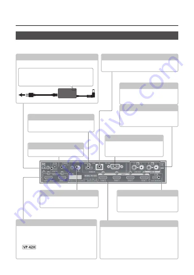
OUTPUT HDMI 1, 2 connectors
These output video and audio. Connect them to a
projector, video recorder, or external display.
5
The menu is shown on the monitor connected to the
OUTPUT HDMI 2 connector.
5
The same video is output from the OUTPUT HDMI 1
and 2 connectors.
RS-232 connector
You can connect this to a computer
equipped with an RS-232 connector,
and remotely control this unit.
USB MEMORY port
You can connect a USB flash drive here
This is used to load still images or to
update the system program.
Ground terminal
Connect this to an external earth or
ground. Connect this if necessary.
INPUT HDMI 1–4 connectors
These input video and audio. Connect them to a
video device such as a video camera or BD player,
or to a computer.
5
The input format is automatically recognized.
5
In the Input menu, the “Input Status” shows the
video format that is being input to each channel,
and the presence or absence of an HDCP signal.
LINE OUT jacks
These output the result of mixing the
input audio. Connect these to your
audio recorder, amp, or speakers etc.
LINE IN jacks
These input audio. Connect these to
your audio or video device such as
an audio mixer or CD player.
[POWER] switch
This switch turns the power on/off.
DC IN jack
Connect the included AC adaptor to this jack.
AC adaptor
Power cord
to an AC outlet
Place the AC adaptor so the side with the indicator
faces upwards and the side with textual information
faces downwards. The indicator will light when you
plug the AC adaptor into an AC outlet.
Rear Panel
* To prevent malfunction and equipment failure, always turn down the volume, and turn off all the units before
making any connections.
USB port
You can connect a USB flash drive here.
This is used to update the system program.
LAN port
This is used to remotely control this unit from a
web browser or terminal software.


