background image

34

Video Composition Operations

Finely adjusting the key color

You can make fine adjustments to the key color.
Use the [MENU] button 

Ó

 “DSK” 

Ó

 “DSK 1” or “DSK 2” to make the 

settings for the following menu items.

Menu item

Explanation

CHROMA

HUE WIDTH

Adjusts the hue width.

HUE FINE

Adjusts the center position of the hue.

SATURATION WIDTH

Adjusts the saturation width.

SATURATION FINE

Adjusts the center position of saturation.

Modifying the superimposed video

You can fill-in the superimposed video, or add an edge to it.
Use the [MENU] button 

Ó

 “DSK” 

Ó

 “DSK 1” or “DSK 2” to make the 

settings for the following menu items.

Menu item

Explanation

FILL TYPE

If this is set to “MATTE,” the superimposed video is 

filled in with the color specified in “MATTE COLOR.”

MATTE COLOR

EDGE TYPE

Specifies the type of edge.

EDGE COLOR

Specifies the color of the edge.

EDGE WIDTH

Specifies the width of the edge.

* This setting is in common with luminance key (p. 31).

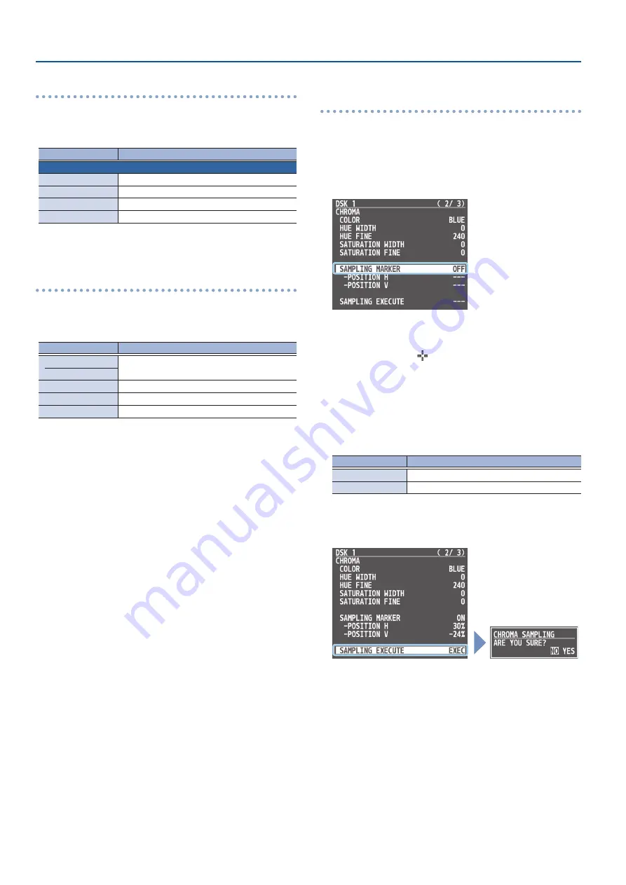
Specifying a desired color as the key color 

(sampling marker)

You can specify the key color to be made transparent by sampling 

(detecting) a color from the video (sampling marker function).
You can also specify a key color other than green or blue.

1 . 

[MENU] button 

Ó

 “DSK” 

Ó

 “DSK 1” or “DSK 2 

Ó

 select 

“SAMPLING MARKER,” and press the [VALUE] knob.

2 . 

Use the [VALUE] knob to select “ON,” and press the 

[VALUE] knob.

The sampling marker (

) used to sample (detect) the key color 

is shown on the monitor of this unit and in the HDMI OUT 3 

connector’s output video.

3 . 

Use the [VALUE] knob to select “POSITION H” or  

“POSITION V,” and press the [VALUE] knob.

4 . 

Use the [VALUE] knob to adjust the position of the 

sampling marker.

Menu item

Explanation

POSITION H

Adjusts the horizontal position.

POSITION V

Adjusts the vertical position.

5 . 

Use the [VALUE] knob to select “SAMPLING EXECUTE,” and 

press the [VALUE] knob.

A confirmation message appears.

*  If you decide to cancel, press the [EXIT] button.

6 . 

Use the [VALUE] knob to select “YES,” and press the 

[VALUE] knob.

The key color is sampled.
The “HUE WIDTH,” “HUE FINE,” “SATURATION WIDTH,” and 

“SATURATION FINE” settings are adjusted automatically.

7 . 

Press the [MENU] button to quit the menu.

Summary of Contents for V-160HD

Page 1: ...02 2021 Roland Corporation Reference Manual ...

Page 2: ...29 Ä ÄCompositing Video with Downstream Keyer DSK 30 About DSK Mode 30 Compositing a Caption or Image Luminance Key 31 Compositing a Subject and Background Chroma Key 33 Compositing a Still Image with Alpha Channel 35 Using an External Key 36 Audio Operations 37 Ä ÄAdjusting the Input Gain Sensitivity 37 Ä ÄAdjusting the Volume Balance 38 Ä ÄApplying Effects to Input Audio 39 Suppressing Echo in a...

Page 3: ...N TIME 77 5 MIX WIPE 78 6 SPLIT 78 7 PinP KEY 79 8 DSK 81 9 AUDIO INPUT 82 10 AUDIO OUTPUT 88 11 AUDIO FOLLOW 90 12 AUDIO AUTO MIXING 90 13 PRESET MEMORY 91 14 MACRO 92 15 SEQUENCER 93 16 STILL IMAGE 93 17 FREEZE 94 18 AUTO SWITCHING 94 19 CTL EXP 95 20 RS 232 TALLY GPO GPI 97 21 LAN CONTROL 98 22 CAMERA CONTROL 99 23 USB MEMORY 100 24 SYSTEM 100 Ä ÄList of Shortcut Keys 104 Appendix 105 Ä ÄAbout ...

Page 4: ... Turns the freeze function freeze the input video on off USER 2 AUTO SWITCHING Turns the auto switching function used to automatically switch between videos on off USER 3 REC CONTROL Controls the recorder s video record start stop if a recorder that supports REC control functionality is connected USER 4 CAMERA CONTROL Turns the camera control function on off When this is on lit the 7 CAMERA PRESET...

Page 5: ...s shown in the right or lower area Turn while pressing Adjusts the position of the boundary 9 SPLIT 1 SPLIT 2 buttons Turns on off video compositing using split p 27 10 PGM A cross point 1 10 buttons Selects the video to input to bus PGM A The selected button lights up 11 PST B cross point 1 10 buttons Selects the video to input to bus PST B The selected button lights up 12 INPUT ASSIGN button Pre...

Page 6: ...ected to the HDMI OUT 3 connector 20 EXIT button Returns you to the menu one level higher 21 VALUE knob Selects a menu item or edits the value of a setting Press this knob to confirm the menu item you selected or the value that you edited 22 OUTPUT FADE button The final output video and audio fade in out Lit Fade out completed Blinking Now fading in out Unlit Normal output 23 SEQUENCER Use this to...

Page 7: ...tton Turns the power on off 11 AUDIO OUT jacks XLR RCA These jacks output audio Choose the jacks that are appropriate for the connected devices For each jack you can change the audio bus MASTER OUTPUT AUX that is assigned for output from that jack 12 AUDIO IN 1 2 3 L 4 R jacks These jacks input audio Choose the jacks that are appropriate for the connected devices About phantom power You can supply...

Page 8: ... and press the VALUE knob A confirmation message appears If you decide to cancel press the EXIT button 5 Use the VALUE knob to select YES and press the VALUE knob Pairing begins 6 Turn on the Bluetooth function of the Bluetooth device 7 Display the Bluetooth device screen on your Bluetooth device and select Roland V 160HD Audio Once pairing is successful the message on the V 160HD changes to COMPL...

Page 9: ...ug To prevent the batteries from running down remove the plugs from the jacks when you re not using the BOSS FS 6 MODE POLARITY switch FS 5U FS 6 FS 7 FS 5U x 2 Stereo 1 4 phone type Ñ Ò 1 4 phone type x 2 CTL B CTL A TIP RING FS 5U x 1 CTL B 1 4 phone type Ñ Ò 1 4 phone type FS 6 CTL B CTL A Stereo 1 4 phone type Ñ Ò Stereo 1 4 phone type FS 7 Stereo 1 4 phone type Ñ Ò Stereo 1 4 phone type CTL B...

Page 10: ...to turn off the power Operating the Menu Here s how to access the menu and make video audio settings and settings for this unit The menu is also appears on the display connected to the HDMI OUT 3 connector 1 Press the MENU button to display the menu The menu is organized into functions 2 Turn the VALUE knob to select the menu item that you want to edit and press the VALUE knob to confirm 3 Repeat ...

Page 11: ...3 16 STILL VIEW button Shows the loaded still images in 16 separate sections on the screen MONITOR 4 PROGRAM button Shows the final output video Audio level meter indication Red Excessive Yellow Suitable Green Insufficient dB 30 20 6 0 50 You can set the audio level meter to show or hide You can also individually set where each audio level meter in the multi view is displayed Configure the setting...

Page 12: ...ssive conversion and is not a malfunction About frame rat The frame rates 59 94 Hz 60 Hz and 50 Hz are supported for output video To make this setting use the MENU button Ó SYSTEM Ó FRAME RATE You can set the frame rate for USB output from the MENU button Ó SYSTEM Ó FRAME RATE USB OUT Setting the Input Format for the HDMI IN 5 8 Connectors Using the factory settings the EDID assignment for the HDM...

Page 13: ...appropriately for the device that s receiving the V 160HD s output 1 MENU button Ó VIDEO OUTPUT Óselect HDMI OUT 1 3 or SDI OUT 1 3 and press the VALUE knob 2 Use the VALUE knob to select a menu item shown below and press the VALUE knob HDMI OUT 1 3 Value Explanation OUTPUT STATUS Shows the format and an HDCP signal presence COLOR SPACE Specifies the color space DVI D HDMI SIGNAL Specifies the typ...

Page 14: ...xplanation PROGRAM Final output video SUB PROGRAM Same video as the PROGRAM bus The SUB PROGRAM bus lets you set whether to display or hide the PinP key layers and the DSK layers separately from the PROGRAM bus You can edit the layer settings to output a different video from that of the PROGRAM bus PREVIEW Preview output video the video to be output next The fade in out effect p 26 is not reflecte...

Page 15: ...MANUAL LINK p 101 Inputting Copy Protected HDCP Video If you want to input HDCP protected video from a BD player or other device you can enable HDCP input If you want to output copy protected HDCP video or audio connect a device that supports HDCP What s HDCP HDCP is copyright protection technology that prevents unlawful copying of content by encoding the path when sending digital signals from a v...

Page 16: ...and tri level synchronizing signals are supported SDI 1 8 A signal input via one of the SDI IN 1 8 connectors is used as the reference clock The VSYNC vertical synchronizing signal output from the V 160HD is synchronized to the VSYNC signal input via SDI When set to EXTERNAL or SDI 1 8 Adjust the following menu items as needed Menu item Explanation CLOCK ADJUST This adjusts the phase horizontally ...

Page 17: ...s the VALUE knob 2 Use the VALUE knob to select A B or PGM PST and press the VALUE knob 3 Press the MENU button to close the menu Switching in the PGM PST Mode Here are the steps when selecting PGM PST mode in the operation mode settings 1 Flip the video fader all the way upward or downward The video on the PGM A bus is the final output When the video fader is pushed all the way down only the topm...

Page 18: ...utput next Lit red Final output video Lit Green Preview output video the video to be output next 3 Press the TRANSITION button to select the transition effect MIX WIPE Using the buttons to switch 4 Press the AUTO or CUT button Button Explanation CUT The picture switches instantly AUTO The video is switched automatically The AUTO button flashes while the video transition is in progress To specify t...

Page 19: ...IPE BORDER WIDTH Changing the Functions of the CUT and AUTO Buttons You can change what happens when you press the CUT and AUTO buttons In PGM PST mode p 17 the functions of the CUT and AUTO buttons are fixed 1 MENU button Ó SYSTEM Óselect CUT SW ASSIGN or AUTO SW ASSIGN and press the VALUE knob 2 Use the VALUE knob to select a function of the button and press the VALUE knob Value Explanation CUT ...

Page 20: ... BPM intervals This lets you create video transitions that are synchronized with the music for example when live streaming a DJ performance or a musical performance TurningtheAutoSwitchingFunctionOn Off 1 MENU button Ó AUTO SWITCHING Óselect AUTO SWITCHING and press the VALUE knob 2 Use the VALUE knob to select ON or OFF 3 Press the MENU button to close the menu MEMO You can assign the function to...

Page 21: ...s the MENU button to close the menu BPM sync 1 MENU button Ó AUTO SWITCHING Óselect TYPE and press the VALUE knob 2 Use the VALUE knob to select BPM SYNC and press the VALUE knob 3 Use the VALUE knob to select a menu item shown below and press the VALUE knob Menu item Explanation BPM Specifies the BPM MODE Specifies how the video is switched TRANSITION The video switches using the currently select...

Page 22: ...lor Resolution In conformity with system format File name No more than 64 single byte alphanumeric characters The extension bmp png or jpg must be added Loading a still image 1 Save the still image in the root directory of the USB flash drive 2 Connect the USB flash drive containing the still image to the USB MEMORY port 3 MENU button Ó STILL IMAGE Óselect LOAD FROM USB MEMORY and press the VALUE ...

Page 23: ...APTURE IMAGE button to exit the operation MEMO You can set the method of saving still images to temporarily save When you turn off the power the captured still image is deleted From the MENU button Ó STILL IMAGE set SAVE TO INTERNAL STORAGE to DISABLE and then capture the image Depending on the format of the input video completion of still image capture might take some time If you capture when HDC...

Page 24: ...Use the VALUE knob to select FILE TYPE and press the VALUE knob Use the VALUE knob to select BITMAP PNG or JPEG and press the VALUE knob 6 Enter a file name You can input up to 16 characters Use the VALUE knob to move the cursor Pressing the EXIT button deletes the character at the cursor location Press the VALUE knob to highlight the character at the cursor location Use the VALUE knob to change t...

Page 25: ...Control Signal p 70 MEMO Outputting a still image with a fade in effect Use the OUTPUT FADE button to add a fade in effect and output the still image Assign a still image to the AUX bus p 15 and edit the function for the OUTPUT FADE button as shown below Use the MENU button Ó SYSTEM Ó and set OUTPUT FADE ASSIGN VIDEO FADE to AUX Freezing the InputVideo Freeze Here s how to temporarily freeze the i...

Page 26: ...ut Unlit Normal output The final output video fades out to a black screen When fade out is complete the OUTPUT FADE button is lit 2 To fade in press the OUTPUT FADE button once again The OUTPUT FADE button blinks and final output begins When fade in is complete the OUTPUT FADE button goes dark MEMO You can use a white screen or the video from the AUX bus to add a fade in out effect To make this se...

Page 27: ... can change the color and width of the boundary To make this setting use the MENU button Ó SPLIT Ó SPLIT 1 or SPLIT 2 Ó BORDER COLOR and BORDER WIDTH Compositing Using SPLIT 1 Press a PGM A cross point 1 10 button to select the video you want to display upper or on the left 2 Press a PST B cross point 1 10 button to select the video you want to display lower or on the right 3 Press the SPLIT 1 or ...

Page 28: ...t the inset screen Knob Explanation POSITION H Adjusts the horizontal position of the inset screen Turn while pressing Adjusts the size of the inset screen POSITION V Adjusts the vertical position of the inset screen Turn while pressing Adjusts the zoom of the video shown in the inset screen 5 Press the PinP KEY 1 PGM button to turn on PinP compositing lit The inset screen is displayed on the fina...

Page 29: ...he PinP KEY 1 4 menu select the copy source and press the VALUE knob to execute Key Compositing the Inset Screen This process makes part of the inset screen transparent and composites the image with the background video You can use luminance key with either a black or a white background or a chroma key with either a blue or green background Luminance key You can cut out text or an image by turning...

Page 30: ...nd video Black or white Background video DSK video source Chroma key p 33 You can cut out a video by turning its blue or green portion transparent and then superimpose it on the background video You can select a color from the video material to set as the key color Blue or green Background video DSK video source Alpha key p 35 Use alpha channels areas which contain transparency data to cut out sti...

Page 31: ...turn it on the button lights up 2 Press a DSK SOURCE 1 10 button to select the DSK video source Magenta DSK video source White Video input available Unlit Video input unavailable Lit magenta When selecting a video not assigned to INPUT 1 10 set this from the MENU button Ó DSK Ó DSK 1 Ó DSK SOURCE 3 Press the DSK 1 PVW button to turn on the preview output lit A preview of the composition results is...

Page 32: ...omposited result that is previewed is sent to final output Modifying the caption or image You can fill in the superimposed caption or image or add an edge to it Use the MENU button Ó DSK Ó DSK 1 or DSK 2 to make the settings for the following menu items Menu item Explanation FILL TYPE If this is set to MATTE the superimposed caption or video is filled in with the color specified in MATTE COLOR MAT...

Page 33: ...ut unavailable Lit magenta When selecting a video not assigned to INPUT 1 10 set this from the MENU button Ó DSK Ó DSK 1 Ó DSK SOURCE 3 Press the DSK 1 PVW button to turn on the preview output lit A preview of the composition results is displayed in the PVW section of the multi view At this stage the final output has not yet been changed 4 Use the DSK 1 LEVEL and GAIN knob to adjust the degree of ...

Page 34: ...sired color as the key color sampling marker You can specify the key color to be made transparent by sampling detecting a color from the video sampling marker function You can also specify a key color other than green or blue 1 MENU button Ó DSK Ó DSK 1 or DSK 2 Óselect SAMPLING MARKER and press the VALUE knob 2 Use the VALUE knob to select ON and press the VALUE knob The sampling marker used to s...

Page 35: ...lain how to composite a still image using DSK 1 The operation is the same when using DSK 2 1 Press the DSK 1 SOURCE button to turn it on the button lights up 2 Press the DSK 1 PVW button to turn on the preview output lit A preview of the composition results is displayed in the PVW section of the multi view At this stage the final output has not yet been changed 3 Press the DSK 1 PGM button to turn...

Page 36: ...DSK SOURCE 1 10 buttons Compositing using DSK Here we explain how to use DSK 1 for compositing videos The operation is the same when using DSK 2 1 Press the DSK 1 SOURCE button to turn it on the button lights up 2 Press the DSK 1 PVW button to turn on the preview output lit A preview of the composition results is displayed in the PVW section of the multi view At this stage the final output has not...

Page 37: ...2 Ó set STEREO LINK to ON When stereo link is turned on the settings of AUDIO IN 1 are applied to AUDIO IN 2 When stereo link is on the AUDIO INPUT LEVEL 2 knob is disabled When phantom power is on and you switch the stereo link setting on off phantom power automatically turns off Adjusting the mic position pan The left right positioning of the sound is called pan If you re using two mics to strea...

Page 38: ...e and press the VALUE knob Press the MENU button to close the menu 3 Use the MASTER OUTPUT knob to adjust the volume of the output The level meter will light yellow at the appropriate volume Indicator Status Red Volume is excessive 0 dB or higher Yellow Volume is appropriate 20 1 dB Green Volume is insufficient 50 21 dB The SIG PEAK indicators for AUX and USB STREAM light up in the same manner MEM...

Page 39: ... maximum volume and minimum volume making the audio more comfortable for listening ÁEqualizer This is a three band equalizer It lets you adjust the volume by boosting or cutting three frequency regions ÁVoice changer p 41 Transforms the pitch or character of the voice ÁDelay p 41 Outputs audio with a delay ÁReverb p 42 Adds reverberation to the sound Using an Effect Preset The V 160HD is equipped ...

Page 40: ...echo canceller turns on 3 Use the VALUE knob to select DEPTH and press the VALUE knob 4 Use the VALUE knob to adjust the depth 1 10 of the echo canceller and press the VALUE knob Use the setting that produces the greatest reduction in the echo 5 Press the MENU button to close the menu MEMO The echo canceller supports rooms that are approximately 20m 215 sq ft If your own voice returns to you as an...

Page 41: ...gs in the negative direction produce a more masculine vocal character and settings in the positive direction produce a more feminine vocal character A setting of 0 is the original voice ROBOT When this is ON the voice is held at a fixed pitch creating a mechanical robot like impression MIX Adjusts the balance between the unprocessed voice 0 and the voice processed by the effect 100 4 Use the VALUE...

Page 42: ...gn the function to a USER button and turn reverb on off p 65 Applying Effects to Output Audio Here s how to modify the tonal character by applying effects The following table shows the effects that are available Audio bus Reverb Equalizer Delay Multi band compressor Limiter MASTER OUTPUT µ µ µ µ µ AUX µ µ 1 MENU button Ó AUDIO OUTPUT Óselect MASTER OUTPUT or AUX and press the VALUE knob 2 Using th...

Page 43: ...r which audio follow is on Controlling theVolume Automatically Auto Mixing The volume adjustments that would normally be done by the operator can be controlled automatically auto mixing function Since this lets you leave the volume adjustments up to the V 160HD it can be used in situations where there is no dedicated operator This is especially useful for meetings discussions debates and other sit...

Page 44: ...the mute function Muting Input Audio 1 MENU buttonÓ AUDIO INPUT Ó AUDIO IN 1 SDI IN 8 Óselect INPUT MUTE and press the VALUE knob 2 Use the VALUE knob to select ON and press the VALUE knob 3 Press the MENU button to close the menu Muting Output Audio This shows you how to mute the audio from the master output USB output and AUX bus 1 MENU button Ó AUDIO OUTPUT Óselect the menu item shown below and...

Page 45: ...MASTER OUTPUT AUX AUX MASTER OUTPUT Output the audio of the MASTER OUTPUT bus AUX Output the audio of the AUX bus 3 Press the MENU button to close the menu Sending Audio to the AUX Bus Use the AUX knob to adjust the volume of audio output from the AUX bus 1 MENU button Ó AUDIO OUTPUT Ó AUX Óselect AUX SEND and press the VALUE knob The AUX SEND menu appears 2 Use the VALUE knob to select the input ...

Page 46: ... making it embedded audio and adding it to HDMI video or SDI video lets you later extract and use the digital audio for the required language 1 MENU button Ó AUDIO OUTPUT Óselect HDMI SDI AUDIO EMBEDDED and press the VALUE knob Assigning the audio 2 Use the VALUE knob to select the HDMI or SDI embedded audio channel and press the VALUE knob 3 Use the VALUE knob to select the input audio you wish t...

Page 47: ...s the MENU button Ó VIDEO OUTPUT Ó USB OUT Ó execute CONNECTION RESET to try reconnecting the computer with the V 160HD Video formats You can change the USB output video format and compression method from the livestreaming app or other app used at the output destination The following video formats are supported USB OUT frame rate Video formats 59 94 Hz 1080 59 94p 720 59 94p 640 x 480 59 94p 29 97...

Page 48: ... memory selection buttons Memory no Button 1 10 MEMORY 1 10 buttons 11 20 PGM A 1 10 buttons 21 30 PST B 1 10 buttons You can prohibit settings from being saved or initialized p 49 to protect the preset memories Use the MENU button Ó PRESET MEMORY Ó and set MEMORY PROTECT to ON Since settings related to the system network and so on are common to the entire unit they are not saved in a memory For d...

Page 49: ...ming a Preset Memory Here s how to rename a preset memory 1 MENU button Ó PRESET MEMORY Óselect NAME EDIT and press the VALUE knob 2 Use the VALUE knob to select the preset memory 1 30 that you want to rename and then press the VALUE knob The PRESET MEMORY NAME screen appears 3 Input the preset memory name You can input up to 8 characters INIT Initializes the name Use the VALUE knob to move the cu...

Page 50: ...elect ADD NEW FUNCTION and press the VALUE knob The FUNCTION EDIT menu appears 4 Use the VALUE knob to select FUNCTION and press the VALUE knob 5 Select the operation to record to the macro using the VALUE knob and then press the VALUE knob For details on the operations you can record see FUNCTION in FUNCTION EDIT p 92 6 Use the VALUE knob to set the related menu item The related menu is shown acc...

Page 51: ...cancel press the EXIT button Use the VALUE knob to select YES and press the VALUE knob The function is moved and the message COMPLETE appears Copying a function Copying is disabled if the number of recorded functions have reached the limit 10 Use the VALUE knob to select COPY THIS FUNCTION and press the VALUE knob The COPY FUNCTION screen appears Use the VALUE knob to select where you want to copy...

Page 52: ...cel press the EXIT button 3 Use the VALUE knob to select YES and press the VALUE knob The macro is executed 4 Press the MENU button to close the menu MEMO Using the cross point buttons to select macros When MACRO is selected on the MODE button the cross point buttons function as macro selection buttons Use the MENU button Ó MACRO Ó and set NUMBER OF MACRO SW to 30 Changing the macro assigned to a ...

Page 53: ...are copied When the operation is finished the message COMPLETE appears 6 Press the MENU button to close the menu Swapping the Macro Settings Here s how to swap settings between macros 1 MENU button Ó MACRO Óselect LIST EDIT and press the VALUE knob 2 Use the VALUE knob to select the swap source macro 1 100 and press the VALUE knob The list of operations recorded in the macro is shown 3 Use the VAL...

Page 54: ...deleted is restored to its factory default settings Renaming a Macro Here s how to rename a macro 1 MENU button Ó MACRO Óselect NAME EDIT and press the VALUE knob 2 Use the VALUE knob to select the macro 1 100 that you want to rename and then press the VALUE knob The MACRO NAME EDIT screen appears 3 Input the macro name You can input up to 8 characters INIT Initializes the name Use the VALUE knob ...

Page 55: ...the EXIT button deletes the character at the cursor location Press the VALUE knob to highlight the character at the cursor location Use the VALUE knob to change the character and press the VALUE knob 5 When you finish entering the name use the VALUE knob to select SAVE and press the VALUE knob A confirmation message appears If you decide to cancel press the EXIT button 6 Use the VALUE knob to sele...

Page 56: ... VALUE knob The macro setting files in the USB flash drive are listed 2 Use the VALUE knob to select the macro settings file that you want to load and press the VALUE knob A confirmation message appears If you decide to cancel press the EXIT button 3 Use the VALUE knob to select YES and press the VALUE knob The macro settings are loaded When the operation is finished the message COMPLETE appears 4...

Page 57: ...EMO The demo data in this unit that s available by factory default includes a list of recorded functions You can completely erase the contents of this list by initializing it p 62 1 MENU button Ó SEQUENCER Óselect LIST EDIT and press the VALUE knob The list of operations recorded in the sequencer is shown 2 Use the VALUE knob to select ADD NEW FUNCTION and press the VALUE knob The FUNCTION EDIT me...

Page 58: ... A confirmation message appears If you decide to cancel press the EXIT button Use the VALUE knob to select YES and press the VALUE knob The function is moved and the message COMPLETE appears Copying a function Use the VALUE knob to select COPY THIS FUNCTION and press the VALUE knob The COPY FUNCTION screen appears Use the VALUE knob to select where you want to copy the function to and then press t...

Page 59: ...cuted PREVIOUS button Press the PREVIOUS button if you want to return to the state at which the previous function was completed 4 Repeat step 3 5 Long press the SEQUENCER ON button again to turn the sequencer function off MEMO Repeatedly executing a function in the list You can repeatedly execute functions that are in a list Once the last function is finished press the NEXT button to execute the f...

Page 60: ...U button to close the menu Running the auto sequence 1 Long press the SEQUENCER ON button to turn the sequencer function on the button lights up The list of operations recorded in the sequencer is shown Check which action is executed when the sequencer moves to the next function When this is set to PAUSE this is blank Long press 2 Press the AUTO SEQUENCE button to turn the auto sequence function o...

Page 61: ...XIT button deletes the character at the cursor location Press the VALUE knob to highlight the character at the cursor location Use the VALUE knob to change the character and press the VALUE knob 5 When you finish entering the name use the VALUE knob to select SAVE and press the VALUE knob A confirmation message appears If you decide to cancel press the EXIT button 6 Use the VALUE knob to select YE...

Page 62: ...LUE knob The sequencer settings are loaded When the operation is finished the message COMPLETE appears 4 Press the MENU button to close the menu Initializing the Sequencer Here s how to initialize the sequencer and erase all the settings 1 MENU button Ó SEQUENCER Óselect INITIALIZE and press the VALUE knob A confirmation message appears If you decide to cancel press the EXIT button 2 Use the VALUE...

Page 63: ... the VALUE knob to change the character and press the VALUE knob 5 When you finish entering the name use the VALUE knob to select SAVE and press the VALUE knob A confirmation message appears If you decide to cancel press the EXIT button 6 Use the VALUE knob to select YES and press the VALUE knob The settings file V16 is backed up on the USB flash drive When the operation is finished the message CO...

Page 64: ...USB flash drive you must use the V 160HD to format it NOTE A USB flash drive that was not formatted by the V 160HD will not be recognized Never turn off the power or remove the USB flash drive while the message PLEASE WAIT is shown When you format a USB flash drive all data on that USB flash drive is erased If the drive contains important data back it up to your computer before you format the driv...

Page 65: ... press a button preset memories 1 30 are recalled in order REC CONTROL Controls the recorder s video record start stop if a recorder that supports REC control functionality is connected p 65 GPO ONE SHOT Outputs a control signal for 0 5 seconds GPO ALTERNATE The control signal output is switched on off while the button is pressed CAMERA CONTROL Turns the camera control function on off Bluetooth CO...

Page 66: ... such as camera position and focus can be registered as presets A registered preset can be recalled when needed Presets are saved in the camera itself 1 MENU button Ó CAMERA CONTROL Ó select CAMERA ID and press the VALUE knob 2 Use the VALUE knob to select the camera that you want to control and press the VALUE knob 3 Use the VALUE knob to select the menu item shown below and press the VALUE knob ...

Page 67: ... settings are recalled from the cameras When the operation is finished the message COMPLETE appears 6 Press the MENU button to close the menu Recalling presets with the buttons By assigning a USER button to the camera control function you can recall presets using the button In this example we ll explain how to use the USER 4 button to recall presets The camera control function is assigned to the U...

Page 68: ...selected in VALUE TAKE Switches the video between PGM A bus and PST B bus AUDIO INPUT MUTE Turns the mute function on off for the input audio AUDIO OUTPUT MUTE Turns the mute function on off for the output audio AUDIO INPUT SOLO Turns the solo function on off for the input audio VOICE CHANGER SW Turns the voice changer on off REVERB MOMENTARY Reverb turns on only while you press the footswitch REV...

Page 69: ...on is completed 6 Press the MENU button to close the menu MEMO You should normally use the EV 5 with its minimum volume knob left in the zero position If you change the position of the minimum volume knob you must execute pedal calibration Assigning a Function to the Pedal You can assign various functions to the expression pedal 1 MENU button Ó CTL EXP Ó CTL EXP 1 or CTL EXP 2 Óselect CTL EXP TYPE...

Page 70: ... functions assigned to GPI 1 8 and then press VALUE ÁCATEGORY Value Explanation N A No function is assigned PGM CH SELECT Switches the PGM A cross point buttons PST CH SELECT Switches the PST B cross point buttons AUX CH SELECT Switches the video sent to the AUX bus INPUT 1 10 ASSIGN Changes the video assigned to INPUT 1 10 STILL OUTPUT Pauses the normal output and previews or final outputs a cut ...

Page 71: ...putting a Control Signal You can use connector pins 1 16 of the TALLY GPIO connector as GPOs to output control signals Assigning the GPOs You can assign pins 1 16 of the TALLY GPIO connector to the GPOs 1 16 in order to output control signals 1 MENU buttonÓ RS 232 TALLY GPO GPI Ó TALLY GPO Óselect TALLY GPO 1 TALLY GPO 16 and press the VALUE knob 2 Use the VALUE knob to select one of GPO 1 GPO 16 ...

Page 72: ...rs When STATUS indicates CONNECTED the connection settings are complete MEMO If you fix the IP address you ll always be able to start Smart Tally with the same IP address For details on how to specify a fixed IP address refer to the manual of the wireless LAN router that you re using Starting SmartTally 1 From the V 160HD s MENU buttonÓ LAN CONTROL Ó select INFORMATION and press the VALUE knob The...

Page 73: ...TURE IMAGE button USER 1 4 SW USER 1 4 buttons AUDIO IN 1 3 4 VOLUME AUDIO INPUT LEVEL 1 2 3 4 knob AUTO MIXING SW AUTO MIXING button AUX VOLUME AUX knob USB STREAM VOLUME USB STREAM knob MASTER OUTPUT VOLUME MASTER OUTPUT knob 3 Use the VALUE knob to specify whether panel lock is enable ON or disable OFF and press the VALUE knob 4 Press the MENU button to close the menu MEMO The MENU button blink...

Page 74: ...able RS 232 connection RS 232 cable USB RS 232 or LAN connection LAN connection V 160HD RCS Computer V 160HD Remote Use the dedicated V 160HD Remote app to operate the V 160HD from your iPad You can connect either wirelessly or via cable Wireless connection Bluetooth connection Connection via wireless LAN master device Wi Fi Wired connection via cable USB connection USB Type C cable Lightning to U...

Page 75: ...M bus video PREVIEW Preview output video This is the default setting for SDI OUT 2 AUX AUX bus video MULTI VIEW Multi view This is the default setting for SDI OUT 3 16 INPUT VIEW The input video from the HDMI IN and SDI IN connectors shown as 16 separate sections on the screen 16 STILL VIEW Still images loaded into the unit shown as 16 separate sections on the screen USB OUT Specifies the video bu...

Page 76: ...source device receives it will output the most appropriate video format to the V 160HD ZOOM 10 0 100 0 1000 0 2 Adjusts the zoom ratio SCALING TYPE Specifies the scaling type FULL Always displays the picture expanded to full screen irrespective of the aspect ratio of the input video LETTERBOX Enlarges or reduces the incoming video to a full screen view while keeping the aspect ratio unchanged CROP...

Page 77: ... and video audio is not outputted from the SDI OUT connectors 3G SDI MAPPING LEVEL A LEVEL B Specifies the mapping structure of the 3G SDI output BRIGHTNESS 64 0 63 Adjusts the brightness CONTRAST 64 0 63 Adjusts the contrast SATURATION 64 0 63 Adjusts the saturation USB OUT Adjusts the video that is output from the USB STREAM port You can edit the USB output video format and compression method fr...

Page 78: ...default value Explanation SPLIT 1 2 These are the detailed settings for the split composite SPLIT OFF ON Turns the split composition on off You can also use the SPLIT 1 or SPLIT 2 button to turn this on off SPLIT TYPE These parameters configure the split screen layout SPLIT V This vertically crops the center section of the video split left right A B A B A B B A SPLIT H This horizontally crops the ...

Page 79: ... RECTANGLE CIRCLE DIAMOND Specifies the shape of the inset screen BORDER COLOR WHITE YELLOW CYAN GREEN MAGENTA RED BLUE BLACK SOFT EDGE Specifies the color of the border for the inset screen When this is set to SOFT EDGE the edge of the inset screen is blurred BORDER WIDTH 0 3 14 Adjusts the width of the border for the inset screen VIEW Adjusts the video that is shown in the inset screen POSITION ...

Page 80: ...5 Adjusts the degree of extraction transparency for the key KEY GAIN 0 255 Adjusts the degree of edge blur semi transmissive region for the key MIX LEVEL 0 255 Adjusts the key s overall density output level CHROMA Make detailed settings for chroma key COLOR GREEN BLUE Specifies green or blue as the key color the color to be removed If you want a color other than green or blue to turn transparent u...

Page 81: ... WITH DSK 2 or DSK 1 EXEC Exchanges the settings of DSK 1 and DSK 2 CHROMA 7 Make detailed settings for chroma key COLOR GREEN BLUE Specifies green or blue as the key color If you want a color other than green or blue to turn transparent use SAMPLING MARKER to specify the key color HUE WIDTH 30 0 30 Adjusts the hue width for the key color HUE FINE 0 240 360 Adjusts the center position of the hue f...

Page 82: ... Hz ECHO CANCELLER OFF ON Turns the echo canceller on off Effect Suppresses the voice echo that can occur when using a web conferencing system that includes a speaker and mic DEPTH 1 5 10 Adjusts the depth of the echo canceller ANTI FEEDBACK OFF ON Turns the anti feedback on off Effect Suppresses audio feedback NOISE GATE OFF ON Turns the noise gate on off Effect Eliminates audio that is lower tha...

Page 83: ... on off Only the audio for which this is ON is heard in the headphones The solo function applies to the headphone output It does not affect output other than the headphones EFFECT PRESET Specifies an effect preset high pass filter compressor and equalizer When you change an effect preset the settings of each effect are overwritten DEFAULT For line input default setting MEETING For meetings INTERVI...

Page 84: ...urns the high pass filter on off Effect Cuts off unneeded low band audio The cutoff frequency is 80 Hz NOISE GATE OFF ON Turns the noise gate on off Effect Eliminates audio that is lower than the specified threshold level This is effective when the noise that you want to remove is separate from the audio that you want to keep and can be used to remove hiss or other noise that is heard during perio...

Page 85: ...e used to remove hiss or other noise that is heard during periods of silence THRESHOLD 80 48 0dB Specifies the level used as the threshold for removing audio Audio below the level set here is removed RELEASE 30 500 5000msec Adjusts the length of time until the audio is fully attenuated after audio falls below the threshold COMPRESSOR OFF ON Turns the compressor on off Effect Audio that exceeds the...

Page 86: ... used to remove hiss or other noise that is heard during periods of silence THRESHOLD 80 48 0dB Specifies the level used as the threshold for removing audio Audio below the level set here is removed RELEASE 30 500 5000msec Adjusts the length of time until the audio is fully attenuated after audio falls below the threshold COMPRESSOR OFF ON Turns the compressor on off Effect Audio that exceeds the ...

Page 87: ...used to remove hiss or other noise that is heard during periods of silence THRESHOLD 80 48 0dB Specifies the level used as the threshold for removing audio Audio below the level set here is removed RELEASE 30 500 5000msec Adjusts the length of time until the audio is fully attenuated after audio falls below the threshold COMPRESSOR OFF ON Turns the compressor on off Effect Audio that exceeds the s...

Page 88: ...ncert hall SIZE 1 10 20 Specifies the size of the room The larger the value the longer the reverb time EQUALIZER OFF ON Turns the equalizer on off Effect Adjusts the volume for each frequency band Hi GAIN 15 0 0 0 15 0dB Boosts or attenuates the high band Hi FREQUENCY 1 00 10 0 20 0kHz Adjusts the center frequency when changing the volume in the high band Mid GAIN 15 0 0 0 15 0dB Boosts or attenua...

Page 89: ...X SEND VIDEO is MANUAL SDI IN 1 8 INF 0dB AUX EFFECT ENTER Displays the AUX EFFECT menu Menu item Value Explanation AUDIO IN 1 3 4 USB IN Bluetooth IN HDMI IN 1 8 SDI IN 1 8 Sets whether to send audio from each input to the AUX bus with effects applied or not DRY Sends the source audio with no effects applied PRE FADER Sends the effect applied audio The send volume is constant regardless of the vo...

Page 90: ... send volume can be changed by adjusting the volume INPUT LEVEL 11 AUDIO FOLLOW Menu item Value bold text default value Explanation ALL AUDIO FOLLOW OFF ON Turns on off the audio follow function for HDMI 1 8 and SDI 1 8 in a single action HDMI 1 8 SDI 1 8 Turns the audio follow function on off Audio follow is a function that automatically switches the audio output in tandem with video switching OF...

Page 91: ...es Protected preset memories are erased if you perform a factory reset NUMBER OF MEMORY SW When MEMORY is selected on the MODE button this sets how many buttons function as memory selection buttons 10 Preset memory 1 10 MEMORY 1 10 buttons 30 Preset memory 1 10 MEMORY 1 10 buttons Preset memory 11 20 PGM A 1 10 buttons Preset memory 21 30 PST B 1 10 buttons FADE TIME 0 0 4 0sec Sets how long the t...

Page 92: ... 100 to the USB flash drive If you selected NEW FILE a new macro settings file is saved NUMBER OF MACRO SW When MACRO is selected on the MODE button this sets how many buttons function as macro selection buttons 10 MACRO 1 10 buttons 30 MACRO 1 10 buttons PGM A 1 10 buttons PST B 1 10 buttons SW ASSIGN ENTER Displays the SW ASSIGN menu Specifies the macro assigned to each button Menu item Value Ex...

Page 93: ... SEQ that are on the USB flash drive You can select a sequence file to save the current sequencer settings to the USB flash drive If you selected NEW FILE a new sequence file is saved 16 STILL IMAGE Menu item Value bold text default value Explanation LOAD FROM USB MEMORY STILL 1 16 Specifies where to save still images imported from a USB flash drive to this unit s internal memory Press the VALUE k...

Page 94: ...re is no video input this is skipped NORMAL Switches in the order of INPUT 1 Ó10 REVERSE Switches in the order of INPUT 10 Ó1 RANDOM Switches randomly SCAN TRANSITION TIME 16 0 0 1 0 4 0sec Specifies the video transition time SCAN TARGET Sets the video to which auto switching is applied PGM A PST B Final output video and preview video PinP KEY 1 4 PinP and key layer inset screen video INPUT 1 10 T...

Page 95: ...ou press the button selected in VALUE TAKE ÇAUTO TAKEÉ Automatically switches the PGM A bus and PST B bus videos ÇCUTÉ Switches the video between PGM A bus and PST B bus as a cut AUDIO INPUT MUTE AUDIO IN 1 3 4 USB IN Bluetooth IN HDMI 1 8 SDI 1 8 Turns the mute function on off for the input audio AUDIO OUTPUT MUTE MASTER OUTPUT AUX USB OUT Turns the mute function on off for the output audio AUDIO...

Page 96: ...AUDIO OUTPUT LEVEL MASTER OUTPUT AUX USB OUT Adjusts the output volume VOICE CHANGER MIX AUDIO IN 1 2 Adjusts the balance between the unprocessed voice 0 and the voice processed by the effect 100 REVERB LEVEL Adjusts the amount of sound that is returned from the reverb return level EXP CALIBRATE ENTER Displays the EXP CALIBRATE screen Following the direction on the screen calibrate adjust the expr...

Page 97: ...video source of the inset screen DSK 1 2 SOURCE SDI Switches the DSK video source SW CONTROL CUT SW AUTO SW TRANSITION SW MODE SW SPLIT 1 SW SPLIT 2 SW PinP KEY 1 4 PVW SW PinP KEY 1 4 PGM SW DSK 1 2 PVW SW DSK 1 2 PGM SW AUTO MIXING SW OUTPUT FADE SW USER 1 4 SW This works the same as when you press the button selected in VALUE TAKE ÇAUTO TAKEÉ Automatically switches the PGM A bus and PST B bus v...

Page 98: ...fault gateway as appropriate for the network to which the unit is connected NETWORK PASSWORD ENTER Displays the NETWORK PASSWORD screen Set the necessary password for network connection using four characters Show password Password not set Password set Input the password that s set here when connecting a computer or other device on the same network to access the V 160HD INFORMATION ENTER Displays t...

Page 99: ...ue you can control the camera LEFT While you hold down the VALUE knob the camera faces left RIGHT While you hold down the VALUE knob the camera faces right TILT Adjusts the vertical position of the camera When the cursor is located at this value you can control the camera DOWN While you hold down the VALUE knob the camera faces up UP While you hold down the VALUE knob the camera faces down SPEED 1...

Page 100: ... one of the SDI IN 1 8 connectors is used as the reference clock The VSYNC vertical synchronizing signal output from the V 160HD is synchronized to the VSYNC signal input via SDI CLOCK ADJUST 1920 0 1920 This adjusts the phase horizontally Adjust this when output is horizontally out of sync with the operation of other devices using the same clock LINE ADJUST 1200 0 1200 This adjusts the phase vert...

Page 101: ... green You can select the video you want to send to the AUX bus Re enabling AUX link AUTO LINK When you operate the AUTO button etc to switch the final output video AUX link is automatically enabled MANUAL LINK When you press the AUX 1 8 button that is currently selected lit green AUX link is enabled CUT SW ASSIGN 20 Specifies the function of the CUT button ÇAUTO TAKE When the video of the PST B b...

Page 102: ... 1 30 are recalled in sequential order REVERSE Each time you press a button preset memories are recalled in reverse order from 30 through 1 REC CONTROL Controls the recorder s video record start stop if a recorder that supports REC control functionality is connected GPO ONE SHOT GPO 1 16 Outputs a control signal for 0 5 seconds GPO ALTERNATE GPO 1 16 The control signal output is switched on off wh...

Page 103: ...ection RIGHT in the multi view LEFT RIGHT PROGRAM Final output video This is the default setting for RIGHT SUB PROGRAM SUB PROGRAM bus video PREVIEW Preview output video This is the default setting for LEFT BLACK Black screen HDMI OUT 3 OSD ENTER Displays the HDMI OUT 3 OSD menu Sets whether to show the menu and other display elements in the video output from the HDMI OUT 3 connector Menu item Val...

Page 104: ... SPLIT 1 button and turn the PGM A CENTER knob SPLIT 2 SPLIT TYPE Hold down the SPLIT 2 button and turn the PST B CENTER knob When the shortcut key is operated the following menu screen is shown Menu Operation DSK 1 Hold down the DSK 1 PVW button and press the MENU button DSK 2 Hold down the DSK 2 PVW button and press the MENU button PinP KEY 1 Hold down the PinP KEY 1 PVW button and press the MEN...

Page 105: ...nction take care not to subject areas protruding beyond the rack to accidental impact To ensure room for connectors and cables leave 2U of clearance above the unit Use all threaded holes at 2 locations on each side for a total of 4 to secure the unit to the rack using screws Screws for rackmounting are not included Never transport the rack with the unit installed in it The impact of shaking or vib...

Page 106: ... 50p 720 59 94p 720 50p 1080 59 94i 1080 59 94p 1080 50i 1080 50p 1080 60p 1080 25p 1080 29 97p 1080 30p 1080 23 98p 1080 24p 1080 23 98p 1080 24p VGA 640 x 480 60 Hz VGA 640 x 480 60 Hz SVGA 800 x 600 60 Hz SVGA 800 x 600 60 Hz XGA 1024 x 768 60 Hz XGA 1024 x 768 60 Hz WXGA 1280 x 800 60 Hz WXGA 1280 x 800 60 Hz SXGA 1280 x 1024 60 Hz SXGA 1280 x 1024 60 Hz FWXGA 1366 x 768 60 Hz FWXGA 1366 x 768...

Page 107: ... Bluetooth input Linear PCM 24 bits 48 kHz 2 ch HDMI IN Linear PCM 24 bits 48 kHz 2 ch HDMI OUT Linear PCM 24 bits 48 kHz 8 ch SDI IN Linear PCM 24 bits 48 kHz 2 ch Conforms to SMPTE 299M SDI OUT Linear PCM 24 bits 48 kHz 8 ch Conforms to SMPTE 299M Input Connectors Analog AUDIO IN 1 2 Combo type XLR 1 4 inch TRS phone phantom power DC 48 V unloaded maximum 14 mA maximum load AUDIO IN 3 L 4 R RCA ...

Page 108: ... Adaptor Current Draw 2 5 A Power Consumption 55 W Operation Temperature 0 to 40 degrees Celsius 32 to 104 degrees Fahrenheit Dimensions 437 W x 253 D x 103 H mm 17 1 4 W x 10 D x 4 1 16 H inches 480 W x 253 D x 103 H mm 18 15 16 W x 10 D x 4 1 16 H inches When rack mount angles are fitted Weight excluding AC adaptor 3 9 kg 8 lbs 10 oz Accessories Startup Guide Leaflet USING THE UNIT SAFELY AC ada...

Page 109: ...Appendix 109 Dimensions 437 239 4 70 4 41 3 95 5 253 7 5 Unit mm When rack mount angles are attached 463 4 32 1 177 8 242 6 8 10 3 480 4 ...

Page 110: ...Appendix 110 Video Block Diagram SYSTEM FORMAT 1080p 1080i 720p STILL IMAGE OUTPUT Assign for USER SW CTL A B GPI OUTPUT ASSIGN OUTPUT ASSIGN OUTPUT ASSIGN ...

Page 111: ...ed CH4 Embedded CH5 Embedded CH6 Embedded CH7 Embedded CH8 Embedded SOLO SOLO L R AUX SIG PEAK LED L R AUDIO IN 3 4 L R AUDIO EMBEDDED CH3 8 AUDIO EMBEDDED CH3 8 L R L R AUDIO OUT XLR AUDIO OUT RCA INPUT LEVEL AUDIO FOLLOW DELAY DIGITAL GAIN CH1 De embedded CH2 De embedded AUTO MIXING SOLO R CH1 Embedded CH2 Embedded CH3 Embedded CH4 Embedded CH5 Embedded CH6 Embedded CH7 Embedded CH8 Embedded PHO...

Reviews: