background image

4

Jun. 2021

AE-30

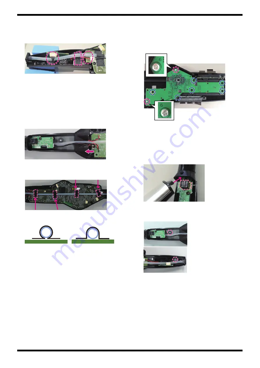
Attaching the Rubber Tube

1.

Give attention to the following points when securing the Tube 
Escutcheon to the Bottom Case using the screws 

c

 (x 2). (

Plain view (2)

View 6

)

fig.kumitate-tb1.eps

The tube must be passed through under the wirings connected to the 
MIDI Board.

The battery wirings must be under the Tube.

An acetate tape must be affixed on the Battery Terminal.

2.

Set the Tube along the arrangement line on the Main Board.

3.

Secure the Mouthpiece Assy to the Bottom Case using the screw 

V

 (x 1). 

(

Plain View (1)

View 1

)

4.

Connect the Sensor Board to the Main Board with the wiring 
(#5100073923).

Arrange the wirings so that they are not on the Main Board.

fig.kumitate-tb2.eps

5.

Secure the Tube on the Main Board with the acetate tape (#40122812). 
(4 locations)

fig.kumitate-tb3-e.eps

fig.kumitate-tb4-e.eps

Attaching the Panel-Center Board

When securing the Panel-Center Board to the Top Case, use two types of 
screws. Use the silver screw (#40011267) at the location where 6 is printed 
near the screw hole on the board.

* If the wrong screw is used, note that the tip of the screw protrudes from the Top 

Case. 

fig.kumitate-panel.eps

Attaching the Top Case Assy

When attaching the Top Case Assy to the Bottom Case, give attention to 
the following points.

1.

Connect the flat cable (1 location) to the Main Board.

2.

Tilt the protrusion (tip) of the Top Case at an angle, insert it into the 
mouse piece holder so as not to touch the breath sensor.

fig.kumitate-top1.eps

3.

Adjust the position of the Top Case Assy so as to fit the Bottom Case 
completely.

Make sure that the protrusions of the Top Case do not pinch the Tube.

fig.kumitate-top2.eps

4.

Secure the Top Case Assy to the Bottom Case using the screw 

s

 (x 1). 

(

Plain view (2)

View 7

)

Near CN19 Next to CN7

Next to CN8

Next to CN6

Tube

Tube

OK

Not OK

Summary of Contents for AE-30

Page 1: ...ons Because reissuance is restricted Because the part is made to order at current market price Because it is carried in electronic data on the Roland web site Because it is a package or an accessory i...

Page 2: ...r Amplifier Power Output 1 5 W x 2 Speakers 2 8 cm x 2 Power Supply AC adaptor DC 5 7 V Rechargeable Ni MH battery AA HR6 sold separately x 6 Current Draw 915 mA Battery life for continuous use Rechar...

Page 3: ...the acetate tape 40122812 so as to cover the locations where the battery terminals and the wirings are soldered fig kumitate tape eps Replacing the Bender Board When replacing the Bender Board verify...

Page 4: ...umitate tb4 e eps Attaching the Panel Center Board When securing the Panel Center Board to the Top Case use two types of screws Use the silver screw 40011267 at the location where 6 is printed near th...

Page 5: ...s g Plain View Fig A View A3 A4 and A5 Also all of No 1 Key Cap A are fixed to No 2 R Key A and No 3 Key Cap B is fixed to No 4 R Key B with adhesive 40122445 fig kumitate button eps About Peripheral...

Page 6: ...tem Backup screen 9 Turn off the power and disconnect the USB memory device Restoring System Settings 1 Hold down MENU and turn on the power Continue to hold down MENU until the Roland logo disappears...

Page 7: ...5 Turn off the power If the message to reset the power is displayed follow it Writing Serial Number When Main Board has been replaced follow the procedure described below to write the serial number in...

Page 8: ...s on the computer just described MIDI OX is available at the following website http www midiox com Mouth piece for test Kindly prepare a product OP AE10MP or OP AE10MPH for inspection purposes Enterin...

Page 9: ...m contrast intermediate contrast maximum 2 Press to advance to the next test item 5 LED This checks whether each LED lights up correctly fig test5 eps The power LED lights up orange and the LED goes o...

Page 10: ...e of the screen is within the range from 110 to 140 10 Press Bend 152 170 is displayed on the screen 11 Flip the bender all the way to the back and verify that the value displayed on the lower line of...

Page 11: ...hecks the operations of the on board speaker the PHONES and OUTPUT jacks fig test8 eps 1 Verify that sounds are coming out from the on board speaker L not from the on board speaker R fig test8 2 eps 2...

Page 12: ...d set Bluetooth on 3 On the Bluetooth setting screen touch AE 30 Audio When pairing succeeds Connected is displayed on the right of AE 30 Audio and the screen display of AE 30 is changed from A2DP to...

Page 13: ...ower is turned off fig test14 eps Return the power switch to the off position This completes the testing in the Test Mode Carry out the following tests in the normal mode 1 Battery Test 1 If an AC ada...

Reviews: